Rail-type conveying device

A conveying device and track-type technology, which is applied in the direction of conveyors, mechanical conveyors, transportation and packaging, etc., can solve the problems of poor positioning accuracy, achieve the effects of short conveying time, avoid product loss, and improve positioning accuracy

Pending Publication Date: 2020-02-21
东莞市钜升智能机械有限公司
View PDF0 Cites 7 Cited by
  • Summary
  • Abstract
  • Description
  • Claims
  • Application Information

AI Technical Summary

Problems solved by technology

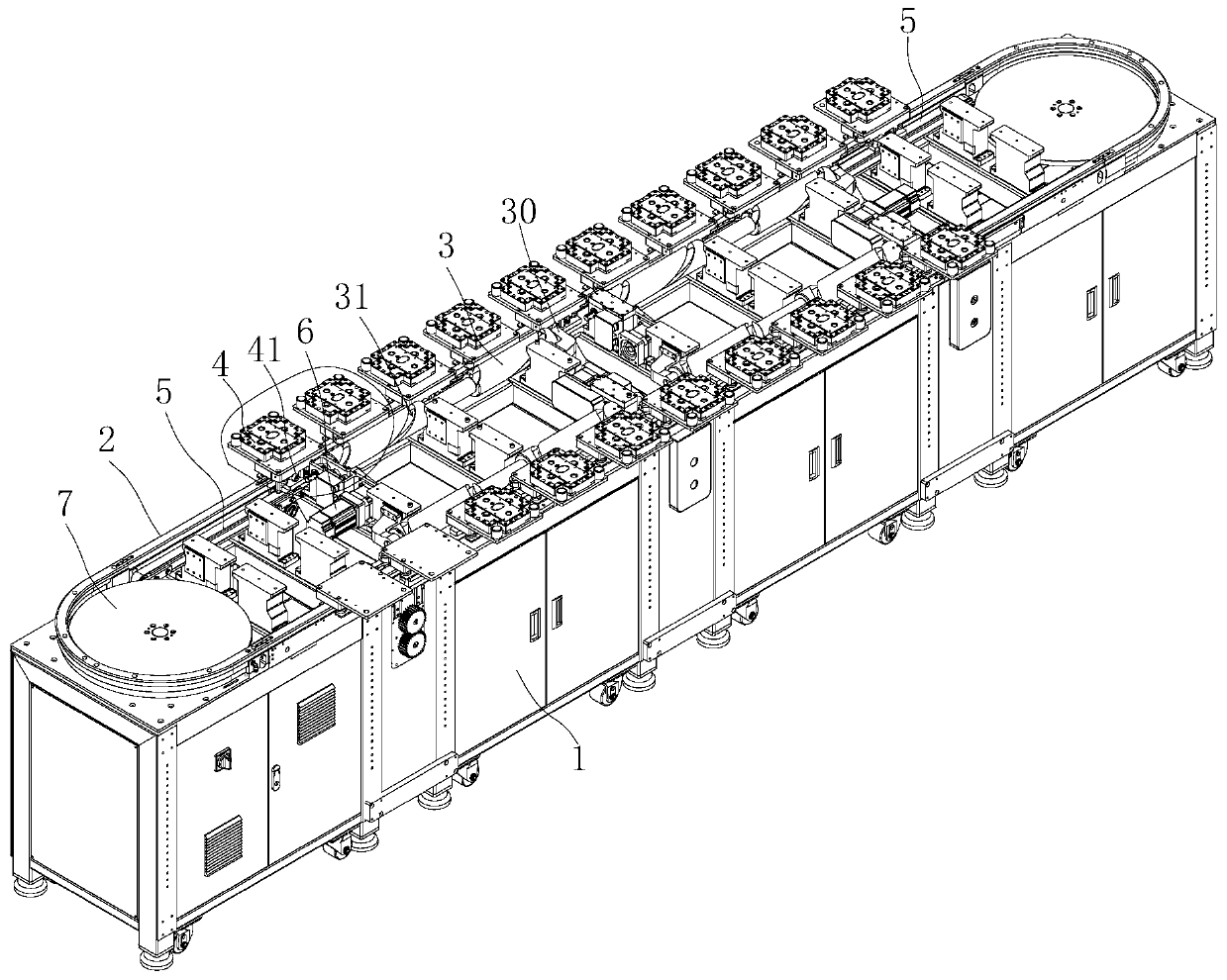
[0003] The object of the present invention is to provide a track-type conveying device, aiming to solve the problem that the conveying mechanism in the prior art is synchronously operated with a positioning jig and the positioning accuracy of the existing conveying mechanism is poor

Method used


Image

  • Rail-type conveying device
  • Rail-type conveying device
  • Rail-type conveying device

Examples


Embodiment Construction

[0024] Embodiments of the present invention are described in detail below, examples of which are shown in the drawings, wherein the same or similar reference numerals designate the same or similar elements or elements having the same or similar functions throughout. The embodiments described below by referring to the figures are exemplary and are intended to explain the embodiments of the present invention and should not be construed as limitations of the present invention.

[0025] In the description of the embodiments of the present invention, it should be understood that the terms "length", "width", "upper", "lower", "front", "rear", "left", "right", "vertical ", "horizontal", "top", "bottom", "inner", "outer" and other indicated orientations or positional relationships are based on the orientations or positional relationships shown in the drawings, and are only for the convenience of describing the embodiments of the present invention and simplifying Describes, but does no...


PUM


Abstract

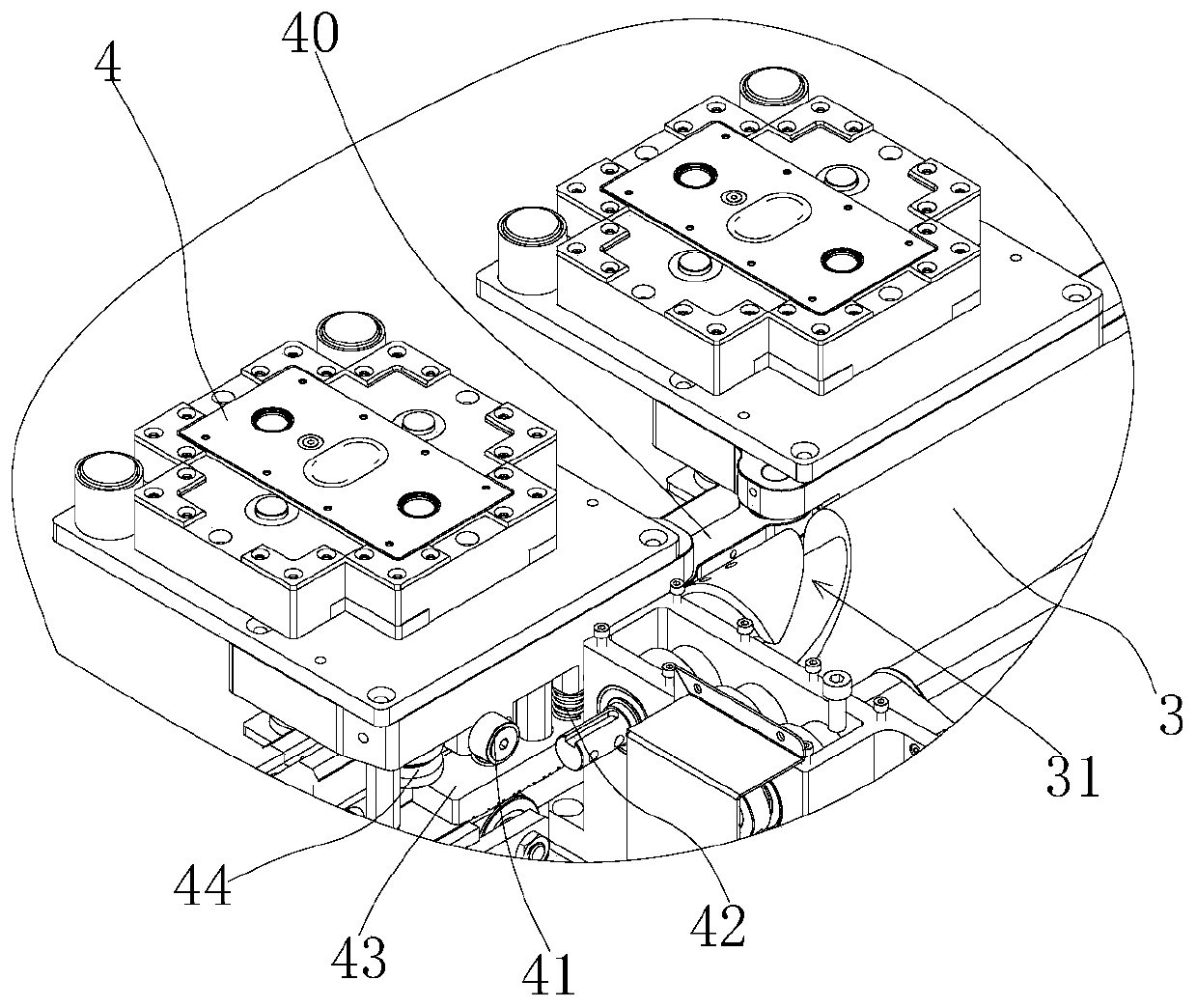
The invention belongs to the field of conveying machinery, and particularly relates to a rail-type conveying device. The rail-type conveying device comprises a rack, pushing mechanisms and a driving piece; a guide rail and a cam shaft are arranged on the rack, and the cam shaft is located on the inner side of the guide rail; supporting seats are arranged at the two ends of the cam shaft in a sleeving mode; the cam shaft is rotationally connected with the two supporting seats, and the two supporting seats are fixedly connected with the rack; a cam groove is formed in the cam shaft, and the twoends of the cam groove extend to the corresponding ends of the cam shaft correspondingly; one or more sets of jig assemblies are arranged on the guide rail, the inner side of at least one positioningjig of each positioning jig assembly is provided with a shifting piece, the driving pieces drive the cam shaft to rotate, and the two ends of the cam shaft are provided with the pushing mechanisms correspondingly; the pushing mechanisms push the positioning jigs located above the pushing mechanisms to move along the guide rail; and the pushing mechanisms push the positioning jigs to be attached tothe cam shaft, the cam shaft rotates, the shifting pieces are guided into the cam groove, and the rotating cam groove pulls the positioning jigs to move along the guide rail.

Description

technical field [0001] The invention belongs to the technical field of conveying machinery, in particular to a track conveying device. Background technique [0002] In the field of automation, conveying and positioning are important components; after the previous process is completed, it is transported and positioned to the next process, so as to complete the next process of the workpiece, realize automatic processing, assembly, etc., to replace manual labor, Improve efficiency. The transmission and positioning mechanism in the prior art usually adopts the mode of belt transmission or chain transmission. However, the belt is a structure and a chain structure, which is integrated; the positioning jig positioned on the belt mechanism or the chain mechanism is transmitted along with the transmission mechanism; therefore, the operation of the positioning jig set on the transmission mechanism is synchronous. However, in the actual process, the working hours required for the upp...

Claims


Application Information

Patent Timeline
Patent Type & Authority Applications(China)
IPC IPC(8): B65G35/06
CPCB65G35/06
Inventor 罗北宋
Owner 东莞市钜升智能机械有限公司
Why Eureka
Try Eureka