Softened water treatment device

A treatment device and water softening technology, which is applied in the field of softened water, can solve the problems of reduced heat exchange effect, blocked water flow channel, and ineffective control of water output, and achieves good softening effect and simple and reasonable structural design

Inactive Publication Date: 2020-02-21
赵东升
View PDF0 Cites 0 Cited by
  • Summary
  • Abstract
  • Description
  • Claims
  • Application Information

AI Technical Summary

Problems solved by technology

[0002] The total amount of calcium and magnesium ions contained in water quality is called the total hardness of water. In the process of daily life and industrial water, insoluble sediment (scale) is easy to be produced, which will bring a lot of inconvenience to life and production, such as: hardness High cooling water will cause the heat exchanger to form scale, seriously hinder the water flow channel, greatly reduce the heat exchange effect, and cause perforation corrosion to damage the equipment
When it is used as boiler water, it will scale on the heating surface of the boiler, and the thermal conductivity will become poor; textile printing and dyeing will cause fabric spots, affecting the appearance and quality of the product, etc.
The working principle of the water softener is to use the exchange effect of the groups in the ion exchange resin to replace and remove the hardness components in the water such as Ca2+, Mg2+ plasma, so as to reduce the harm of scale in the subsequent pipelines and equipment, and prolong the service life of the equipment. Some softening water treatment devices have unreasonable structural design and poor softening effect, resulting in the inability to achieve the purpose of hard water softening and effective control of the water output. Therefore, it is urgent for those skilled in the art to design a new type of softening water treatment device

Method used


Image

  • Softened water treatment device

Examples


Embodiment Construction

[0011] The present invention will be further explained below in conjunction with the accompanying drawings and embodiments.

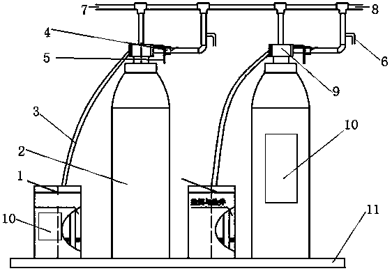
[0012] Such as figure 1 As shown, a softening water treatment device includes a salt storage box 1, a resin tank 2, a salt suction pipe 3, a flow meter 4, a sewage pipe 5, a sampling connection 6, an inlet pipe 7, an outlet pipe 8 and a reaction seat 9 , one end of the salt storage box 1 is provided with a reaction seat 9, the salt storage box 1 communicates with the reaction seat 9 through the salt suction pipe 3, and the bottom end of the reaction seat 9 is equipped with a resin tank 2 and connected to it The upper end of the reaction seat 9 is equipped with a water inlet device and communicated with the water inlet pipe 7, and the reaction seat 9 is provided with a water outlet pipe 8 on one side, and a flow meter 4 is installed on the water outlet pipe 8. One side of the water outlet pipe 8 is provided with a sampling connecting pipe 6, and the oth...


PUM


Abstract

The invention discloses a softened water treatment device. The device comprises a salt storage box body (1), a resin tank (2), a salt absorption pipeline (3) and a flowmeter (4), a blow-off pipe (5),a sampling tubing (6), a water inlet pipeline (7), a water outlet pipeline (8) and a reaction seat (9), wherein the reaction seat (9) is arranged at one end of the salt storage box body (1), the saltstorage box body (1) communicates with the reaction seat (9) through the salt absorption pipeline (3), the resin tank (2) is arranged at the bottom end of the reaction seat (9) and communicates with the same, water inlet equipment is arranged at an upper end of the reaction seat (9) and communicates with the reaction seat (9) through the water inlet pipeline (7), a water outlet pipeline (8) is arranged at one side of the reaction seat (9), the flowmeter (4) is arranged on the water outlet pipeline (8), the sampling tubing (6) is formed in one side of the water outlet pipeline (8), and the blow-off pipe (5) is arranged at the other end of the reaction seat (9). Through the reaction treatment of the salt storage box and the resin tank, the softening effect is good, an aim of softening the hard water can be effectively realized, and the flowmeter can be used for effectively controlling the water yield.

Description

technical field [0001] The invention relates to the technical field of softened water, in particular to a softened water treatment device. Background technique [0002] The total amount of calcium and magnesium ions contained in water quality is called the total hardness of water. In the process of daily life and industrial water, insoluble sediment (scale) is easy to be produced, which will bring a lot of inconvenience to life and production, such as: hardness High cooling water will cause the heat exchanger to form scale, seriously hinder the water flow channel, greatly reduce the heat exchange effect, and cause perforation corrosion to damage the equipment. When it is used as boiler water, it will scale on the heating surface of the boiler, and the thermal conductivity will deteriorate; textile printing and dyeing will cause fabric spots, affecting the appearance and quality of products, etc. The working principle of the water softener is to use the exchange effect of th...

Claims


Application Information

Patent Timeline
IPC IPC(8): C02F1/42
CPCC02F1/42C02F2101/10C02F2209/40
Inventor 赵东升
Owner 赵东升
Why Eureka
Try Eureka