Supercharge Your Innovation With Domain-Expert AI Agents!

Warp beam for textile machinery

A technology of textile machinery and warp beams, applied in the field of textiles, can solve problems such as twisting together and difficulty in sizing process

Inactive Publication Date: 2020-02-21
常州蚕猫网络科技有限公司
View PDF0 Cites 0 Cited by
  • Summary
  • Abstract
  • Description
  • Claims
  • Application Information

AI Technical Summary

Problems solved by technology

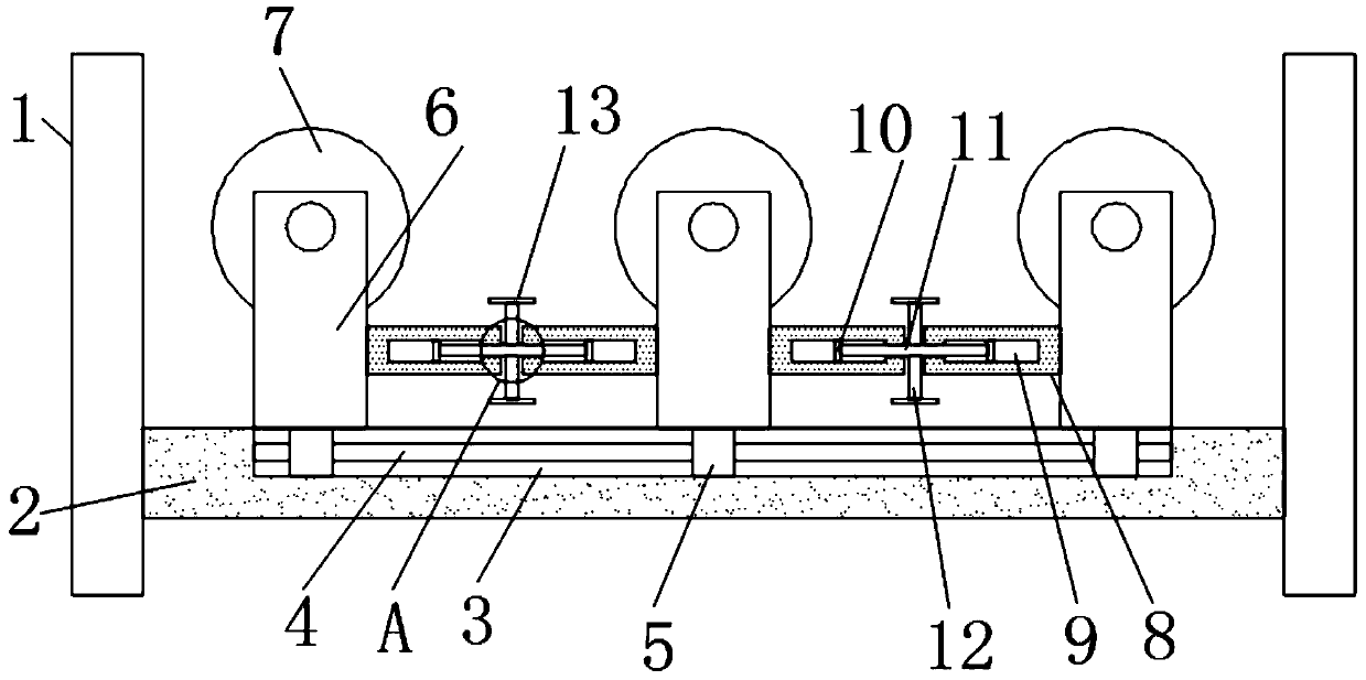
[0005] The purpose of the present invention is to provide a warp beam for textile machinery, to solve the problem that the thickness of the warp yarns on the warp beam will gradually decrease during the sizing process proposed in the above-mentioned background technology, and the frame body supporting the warp beam frame during the sizing process is fixed. As a result, the warp yarn stroke will gradually increase with the sizing process, so the warp yarns are prone to twisting together in the middle and late stages of the sizing process, which brings a certain degree of difficulty to the sizing process.

Method used


Image

  • Warp beam for textile machinery
  • Warp beam for textile machinery

Examples


Embodiment Construction

[0019] The following will clearly and completely describe the technical solutions in the embodiments of the present invention with reference to the accompanying drawings in the embodiments of the present invention. Obviously, the described embodiments are only some, not all, embodiments of the present invention. Based on the embodiments of the present invention, all other embodiments obtained by persons of ordinary skill in the art without making creative efforts belong to the protection scope of the present invention.

[0020] In describing the present invention, it is to be understood that the terms "center", "longitudinal", "transverse", "length", "width", "thickness", "upper", "lower", "front", " Back", "Left", "Right", "Vertical", "Horizontal", "Top", "Bottom", "Inner", "Outer", "Clockwise", "Counterclockwise", "Axial", The orientation or positional relationship indicated by "radial", "circumferential", etc. is based on the orientation or positional relationship shown in ...


PUM


Abstract

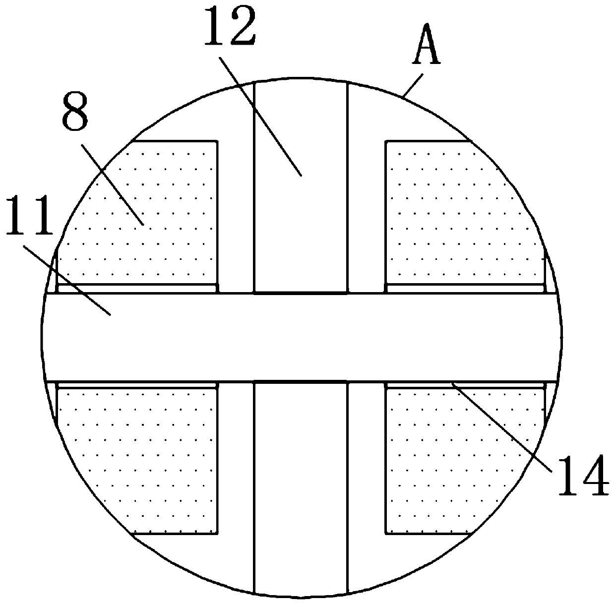
The invention discloses a warp beam for textile machinery, and relates to the textile field. The warp beam for the textile machinery comprises a supporting column, wherein one side of the supporting column is fixedly connected with a supporting plate, the upper surface of the supporting plate is provided with a movable groove, the inside of the movable groove is fixedly connected with a sliding column, the outer side of the sliding column is movably connected with a sliding sleeve, the top of the sliding sleeve is fixedly connected with a supporting frame, and the top of the supporting frame is movably connected with warp beams. The sliding sleeve is provided with an advantageous movable space by forming the movable groove in the supporting plate; the sliding column can facilitate horizontal stable movement of the sliding sleeve and the supporting frame, a connecting rod can rotate conveniently through a handle, and a threaded rotating rod can rotate conveniently through the connectingrod. Through cooperation of the threaded rotating rod and a threaded hole, a connecting arm can be driven to horizontally move, therefore, movement of the supporting frame is realized, and the distances among the warp beams are adjusted through the movement of the supporting frame. The circumstance that warp yarns are twisted together in the middle and later stages of the warp beams is effectively avoided.

Description

technical field [0001] The invention relates to the textile field, in particular to a warp beam for a textile machine. Background technique [0002] The original meaning of textile is taken from the general term of spinning and weaving, but with the continuous development and improvement of the textile knowledge system and subject system, especially after the emergence of non-woven textile materials and three-dimensional composite weaving technologies, the current textile is not only a traditional Hand spinning and weaving, also including non-woven fabric technology, the warp beam is used to fix the warp during weaving, so that the warp is arranged in a certain order and at intervals. [0003] At present, the thickness of the warp yarn on the warp beam will gradually decrease during the sizing process, and the frame body supporting the warp creel frame is fixed during the sizing process, so that the stroke of the warp yarn will gradually increase with the sizing process. Th...

Claims


Application Information

Patent Timeline
Patent Type & Authority Applications(China)
IPC IPC(8): D02H13/38
CPCD02H13/38
Inventor 上官岱意
Owner 常州蚕猫网络科技有限公司
Features
  • R&D
  • Intellectual Property
  • Life Sciences
  • Materials
  • Tech Scout
  • Unparalleled Data Quality
  • Higher Quality Content
  • 60% Fewer Hallucinations
Learn More