A clip-on steel wall panel and its assembly method

A clip-on steel and wall panel technology, which is applied to walls, buildings, building components, etc., can solve the problems of reducing the service life of steel wall panels, exposed cracks at joints, and extrusion of steel plates at joints, etc. The effect of service life, guarantee of flatness, and prevention of large-area deformation

Active Publication Date: 2021-01-05
安徽福瑞尔铝业科技有限公司
View PDF10 Cites 0 Cited by
  • Summary
  • Abstract
  • Description
  • Claims
  • Application Information

AI Technical Summary

Problems solved by technology

[0003] The purpose of the present invention is to provide a clip-type steel wall panel and its assembly method, which can prevent large-area deformation of the steel wall panel, effectively ensure the flatness of the outer wall of the building, have a simple structure, and are easy to operate. The force makes the entire steel wallboard after splicing have a small movement space, which can resist the influence of temperature on the size of the steel wallboard while playing a certain shock absorption function, and has higher practicability. The connection angle between the card slot and the card block is a rigid angle, frequent assembly and disassembly and friction will cause serious wear and tear on the surface of the connection, reducing the service life of the steel wall panel, and the clamping place is mostly the edge of the steel wall panel , there is no supporting structure on the inner side of the steel wall panel, once the inner side of the steel wall panel is hit, it will produce a large area of ​​deformation, and the flatness of the wall surface is poor; the existing clip-on steel wall panel assembly The method uses mechanical components to fix the steel wall panels, and the distance between the steel wall panels and the steel wall panels and the steel wall panels and the wall is fixed, but as the outdoor temperature changes, the material will expand with heat and contract with cold. , leading to changes in the size of the joints between steel wall panels and steel wall panels and between steel wall panels and walls, or causing cracks at the joints to be exposed, or causing steel plates to be squeezed at the joints, which is not practical.

Method used


Image

  • A clip-on steel wall panel and its assembly method
  • A clip-on steel wall panel and its assembly method
  • A clip-on steel wall panel and its assembly method

Examples


Embodiment Construction

[0029] The following will clearly and completely describe the technical solutions in the embodiments of the present invention with reference to the accompanying drawings in the embodiments of the present invention. Obviously, the described embodiments are only some, not all, embodiments of the present invention. Based on the embodiments of the present invention, all other embodiments obtained by persons of ordinary skill in the art without making creative efforts belong to the protection scope of the present invention.

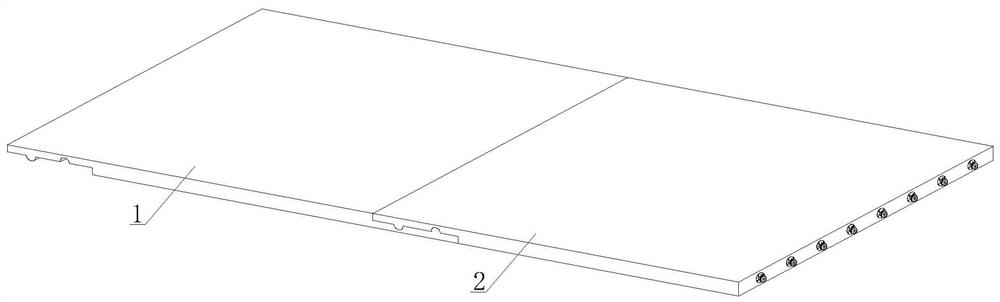
[0030] see figure 1 , a clip-on steel wall panel, including a middle panel assembly 1 and a side panel assembly 2, one side of the side panel assembly 2 is docked with a wall, and the other side of the side panel assembly 2 is docked with the middle panel assembly 1.

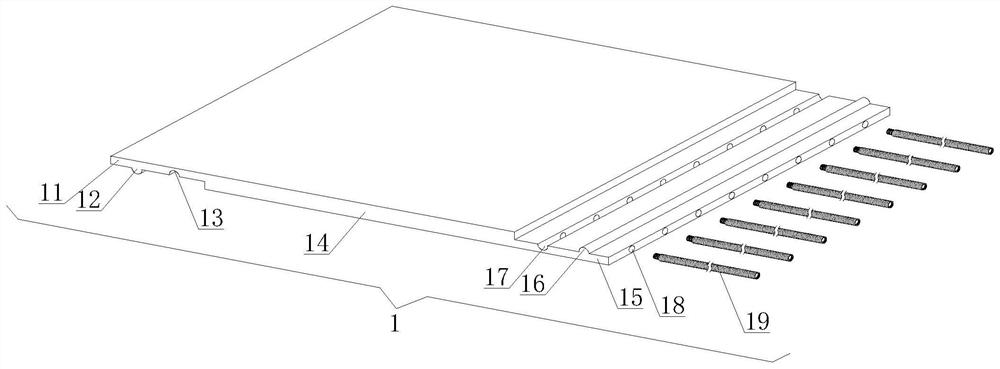
[0031] see figure 2 , the middle board assembly 1 includes an upper docking board 11, a clip A12, a slot A13, a middle board main body 14, a lower docking board 15, a clip B16, a slot B17, a t...


PUM


Abstract

The invention discloses a clamp-type steel wall plate and an assembly method. The clamp-type steel wall plate comprises middle plate assemblies and side plate assemblies, wherein one side of each sideplate assembly is butted with a wall, and the other side of each side plate assembly is butted with the corresponding middle plate assembly, lower butting plates are butted with upper butting plates,and splicing for two adjacent middle plate assemblies is realized, and each clamping bar A and each clamping groove A are configured to be an arc-surface structure separately, so that the wear of thesurfaces of the clamping bars A and the clamping grooves A is reduced; and a plurality of groups of studs are equidistantly arrayed in parallel in the steel wall plate, the steel wall plate is prevented from generating large-area deformation, each clamp structure is butted with a wall embedding structure, and each whole clamp structure is enabled to feed towards the direction of the correspondingwall embedding structure due to the restoring force of an elastic block, so that close bonding between the clamp structure and the corresponding wall embedding structure is realized, each whole sideplate assembly is fixed into a wall body, the whole spliced steel wall plate has a small-amplitude moving space due to the buffer force of the elastic blocks, the influence of a temperature on the dimension of the steel wall plate can further be resisted while a certain shock absorption function is realized, and higher practicability is achieved.

Description

technical field [0001] The invention relates to the technical field of wallboard assembly, in particular to a clip-on steel wallboard and an assembly method. Background technique [0002] As one of the wall materials for public spaces, steel wall panels are more and more popular with designers and customers for their properties such as scratch resistance, fire protection, environmental protection, moisture resistance, prefabricated installation, piping routing, antibacterial and no radiation. It is a good choice to replace traditional wall materials. During the installation of steel wall panels, small-area steel wall panels are installed in an integral way. For large-area steel wall panels, screws are usually used. The way to fix the steel wallboard on the wall, and the screw is fixed on the surface of the steel wallboard, which has a bad influence on the appearance of the steel wallboard surface, so the snap-fit ​​installation method is generally used in the prior art, and ...

Claims


Application Information

Patent Timeline
Patent Type & Authority Patents(China)
IPC IPC(8): E04B2/00E04C2/30
CPCE04B2/00E04C2/30
Inventor 刘露于亚民韦茂忠何世发
Owner 安徽福瑞尔铝业科技有限公司
Why Eureka
Try Eureka