Reinforcement device and method for bent pressure rod
A technology of reinforcement device and compression rod, which is applied in building maintenance, construction, building structure, etc., can solve the problems of small contribution to stable bearing capacity, difficulty in manufacturing restraint components, and buckling instability of components, so as to improve adaptability and strengthen The method is simple and effective, and the effect of improving economic efficiency
- Summary
- Abstract
- Description
- Claims
- Application Information
AI Technical Summary
Problems solved by technology
Method used
Image
Examples
Embodiment 1
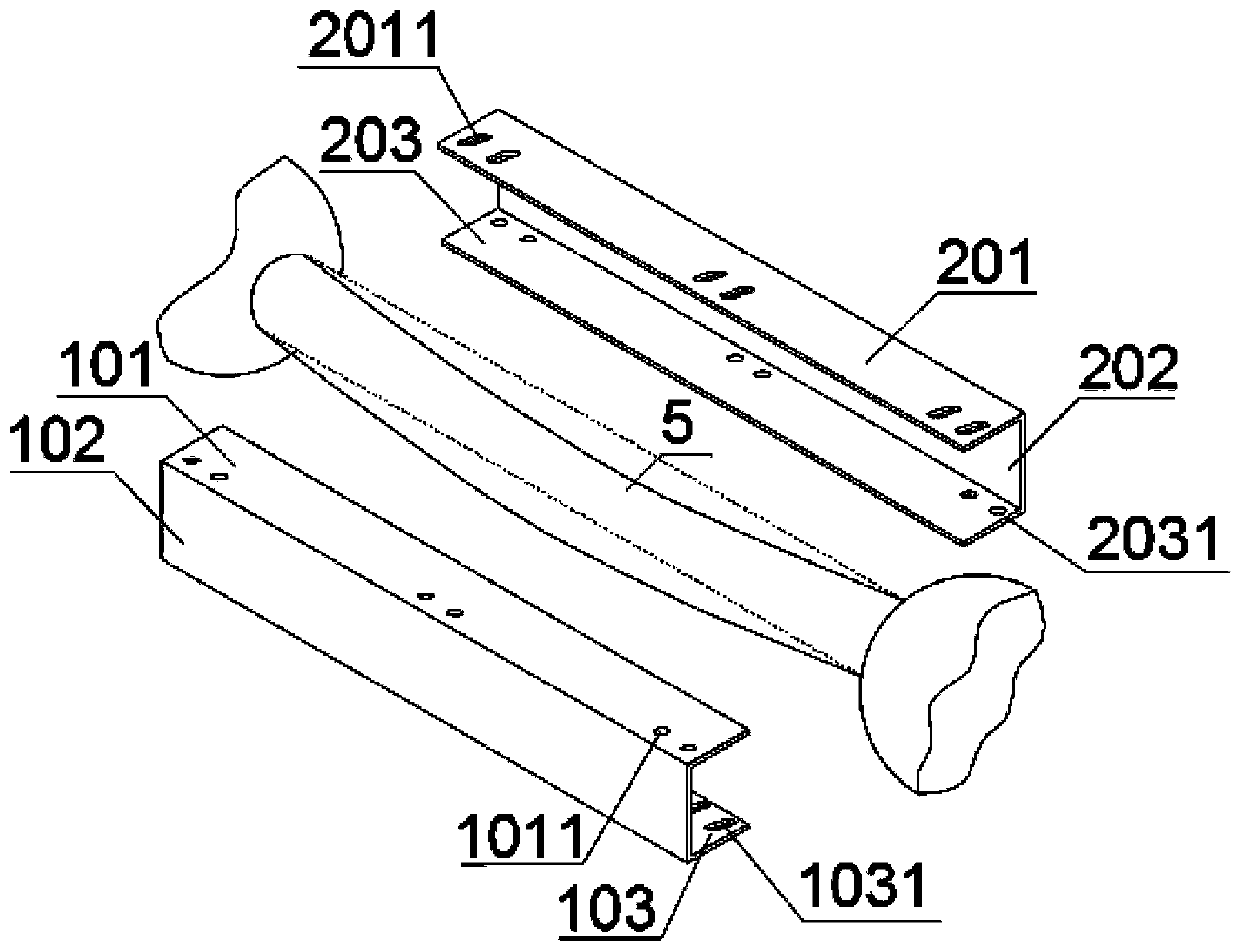
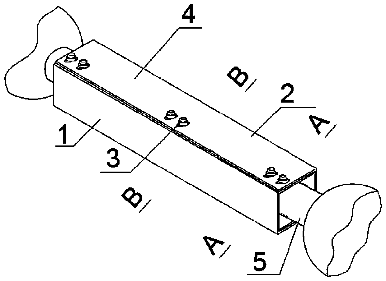
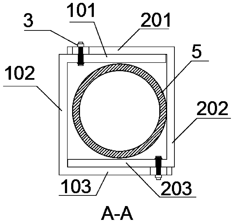
[0035] Such as Figure 1~6 , the curved compression bar 5 is in the shape of a curved round bar, and the reinforcing components used are two first U-shaped steel 1 and second U-shaped steel 2 whose length is slightly shorter than the curved compression bar 5 . A round hole 1011 is formed on the first flange 101 of the first U-shaped steel 1 , and a slot 1031 is formed on the second flange 103 . There is a second slot hole 2011 on the third flange 201 of the second U-shaped steel 2 , and a second round hole 2031 is arranged on the fourth flange 203 . The first U-shaped steel 1 and the second U-shaped steel 2 are identical. The first flange 101 , the second flange 103 , the third flange 201 , and the fourth flange 203 are parallel to the initial deflection direction of the bending strut 5 . The first U-shaped steel 1 and the second U-shaped steel 2 are arranged oppositely, the first flange 101 overlaps the third flange 201 , and the second flange 103 overlaps the fourth flange...
Embodiment 2
[0037] Such as Figure 7-10 , The difference between this embodiment and Embodiment 1 is that the two ends of the bending bar 5 are welded with stiffeners 6 along the axial direction of the bent bar 5 close to the support, and two stiffeners 6 are welded symmetrically at each end, and the stiffeners 6 are welded at the restraining part In the gap formed by the corner of 4 and the surface of the curved strut 5. The length of the stiffener 6 is greater than the cross-sectional outer diameter of the bent strut 5 . A positioning pin 7 is arranged in the middle of the bending compression bar 1, and the positioning pin 7 passes through the first web 102 or the second web 202, and other parts are the same as in the first embodiment.
Embodiment 3
[0039] Such as Figure 11 The difference between this embodiment and Embodiment 1 is that after the first U-shaped steel 1 and the second U-shaped steel 2 are overlapped by dislocation, the tail of the third flange 201 can be welded to the first flange 101 through the welding seam 8 , the tail of the second flange 103 is welded on the fourth flange 203, and other parts are the same as in Embodiment 1.
PUM
 Abstract
Description
Claims
Application Information
 - R&D
- Intellectual Property
- Life Sciences
- Materials
- Tech Scout
- Unparalleled Data Quality
- Higher Quality Content
- 60% Fewer Hallucinations
Browse by: Latest US Patents, China's latest patents, Technical Efficacy Thesaurus, Application Domain, Technology Topic, Popular Technical Reports.
© 2025 PatSnap. All rights reserved.Legal|Privacy policy|Modern Slavery Act Transparency Statement|Sitemap|About US| Contact US: help@patsnap.com


