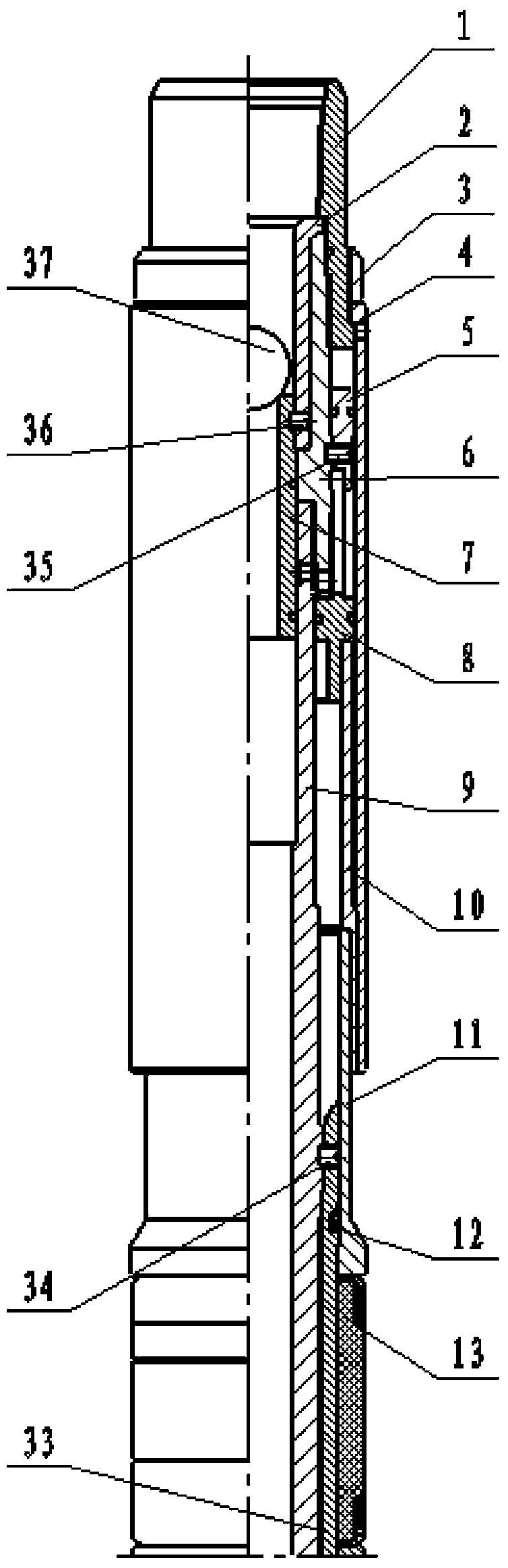
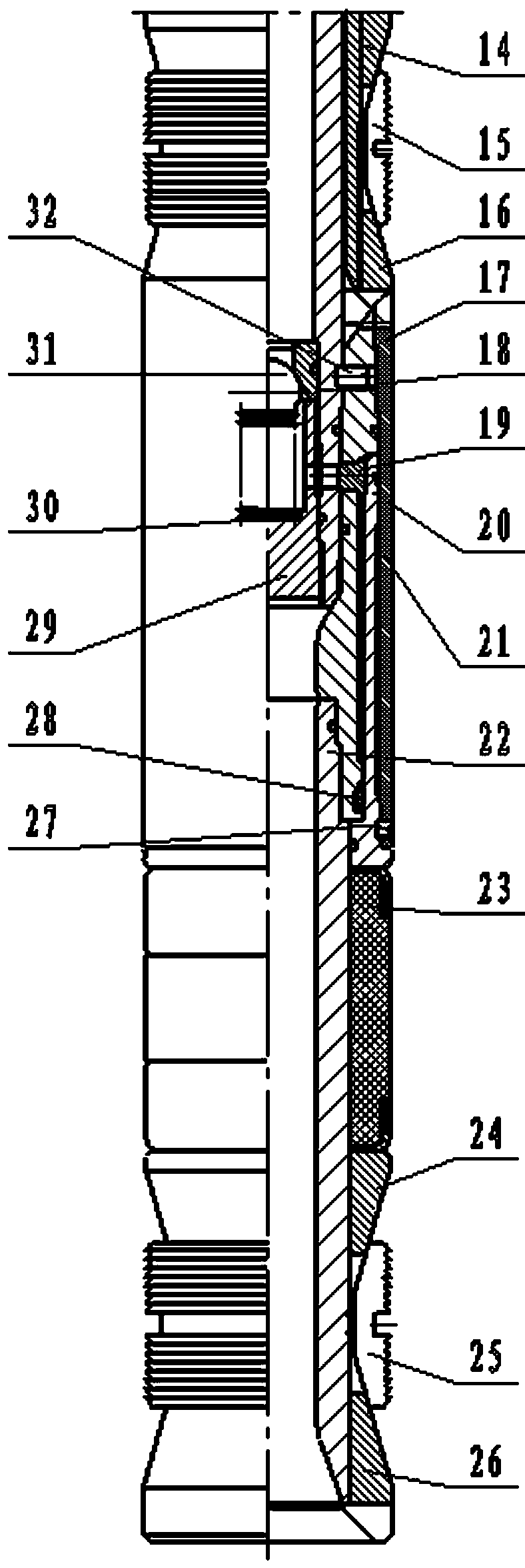
[0022] The present invention will be further explained below in conjunction with the drawings and embodiments.
[0023] Such as figure 1 , 2 As shown, upper joint-1, positioning sleeve-2, back cap-3, cylinder tube-4, auxiliary piston-5, connecting sleeve-6, sliding sleeve-7, main piston-8, center tube-9, thrust sleeve -10, ball seat-18, retaining ring-29, spring-30, steel ball Ⅰ-31, steel ball Ⅱ-37 constitute the sealing tool.
[0024] Upper pressure ring-11, lock spring I-12, rubber cylinder-13, upper cone I-14, upper slip-15, lower cone I-16, rubber cylinder shaft-33, auxiliary piston shear nail- 35. Sliding sleeve shear nail-36 constitutes an upper blocking tool.
[0025] Seal sleeve-17, clamp -19, lower main piston-20, lower cylinder liner-21, lower rubber cylinder shaft-22, lower rubber cylinder-23, upper cone Ⅱ-24, lower slip-25, lower cone Body Ⅱ-26, setting shears-27, and lock spring Ⅱ-28 constitute the lower blocking tool.
[0026] The upper plugging tool is fixed to the center tube-9 on the sealing tool by the hand-off scissors Ⅱ-34, and the lower blocking tool is fixed on the center tube-9 on the sealing tool by the hand-off scissors Ⅰ-32.
[0027] Both the upper and lower plugging and plugging tools are made of drillable materials. After the upper and lower plugging tools are thrown away, they are left in the well without connection to the tubing.
[0028] The ball seat-18 is set in the center tube-9 and is limited by the shoulder of the center tube-9. The steel ball I-31 is installed in the ball seat-18, and the spring-30 is installed in the retaining ring-29. The retaining ring -29 is threadedly connected with the central pipe-9, and the retaining ring -29 is threadedly connected with the central pipe-9. The spring -30 is in contact with the steel ball I-31, and the steel ball I-31 is pressed against the ball seat-18. The gluing barrel shaft-33 is set on the center tube-9, and is limited by the outer circle shoulder of the center pipe-9, and the cut nail Ⅱ-34 penetrates the gluing barrel shaft-33 set and the center tube-9. The lock spring I-12 is installed in the gluing cylinder shaft-33 ring groove. The upper pressure ring -11 is inserted from under the rubberizing cylinder shaft-33, sleeved on the rubberizing cylinder shaft-33, and tightly attached to the shoulder of the rubberizing cylinder shaft-33. The gluing cylinder-13 penetrates under the gluing cylinder shaft-33, is sleeved on the gluing cylinder shaft-33, and is close to the right end surface of the upper pressure ring-11. The upper cone I-14 penetrates under the glue cylinder shaft-33, sleeves it on the glue cylinder shaft-33, and is close to the right end surface of the glue cylinder-13. The upper slip -15 penetrates under the glue cylinder shaft -33, and is sleeved on the glue cylinder shaft -33. The upper slip -15 slope is close to the upper cone I-14 slope, and the lower cone I-16 is Gluing barrel shaft -33 threaded connection, the inclined surface of the lower cone Ⅰ-16 and the inclined surface of the upper slip -15 are closely attached. The clamp -19 and the lock spring II-28 are respectively installed in the groove of the sealing sleeve-17, and the sealing sleeve-17 is sleeved on the central tube-9, and the relative position is fixed by the clamp -19. The lower cylinder liner-21 is threadedly connected with the sealing sleeve-17. Throw away the scissors nail I-32 and penetrate into the sealing sleeve-17 and the center tube-9. The lower main piston -20 penetrates under the seal sleeve -17, is sleeved on the seal sleeve -17, is limited by the shoulder of the left end of the seal sleeve -17, and presses the block -19. The setting shear nail -27 penetrates between the lower cylinder liner -21 and the sealing sleeve -17. The lower rubber cylinder shaft-22 penetrates under the sealing sleeve-17 and is threadedly connected with the sealing sleeve-17. The lower rubber cylinder -23 penetrates under the lower rubber cylinder shaft -22, close to the right end of the lower main piston -20, and the upper cone Ⅱ-24 penetrates under the lower rubber cylinder shaft -22, and adheres to the lower rubber cylinder -23. On the right end surface, the lower slip -25 penetrates under the lower rubber cylinder shaft -22, and the inclined surface is tightly attached to the upper cone Ⅱ-24. The lower cone Ⅱ-26 penetrates under the lower rubber barrel -22 and is threadedly connected with the lower rubber barrel -22. The thrust sleeve-10 is sleeved on the upper pressure ring-11 and is limited to the left end surface of the upper pressure ring-11. The main piston-8 is threadedly connected with the thrust sleeve-10. The connecting sleeve-6 is threadedly connected with the upper end of the center tube-9. The secondary piston-5 is sleeved on the connecting sleeve-6. The auxiliary piston shear nail-35 is connected to the auxiliary piston-5 sleeve and the connecting sleeve-6. Positioning sleeve-2 is placed on the sliding sleeve-7, is limited by the shoulder of the sliding sleeve-7, the shear nail-36 penetrates into the positioning sleeve-2 and sliding sleeve-7, and the positioning sleeve-2 is limited to the connecting sleeve-6 Upper end face. The upper joint-1 is threadedly connected with the connecting sleeve-6. Cylinder-4 is sleeved on thrust sleeve-10, and the limit and upper joint-1 shoulder. The back cap-3 and the upper joint-1 are threadedly connected.
[0029] Work flow: After connecting the packer string with 2 7/8TBG tubing, pressurize the tubing, compress the spring -30, push the steel ball I-31, lower the main piston -20 and go down, and cut off the setting shear nail- 27. The lower main piston-20 pushes the lower rubber cylinder-23 to seal, the lower rubber cylinder-23 is close to the casing wall, the upper cone Ⅱ-24 goes down, pushes the lower slip-25 to expand, and the lower slip-25 wedge Between the lower cone Ⅱ-26 and the casing wall, the lock spring Ⅱ-28 and the lower main piston -20 are locked at the same time, and the lower packer is sealed. Lift up the pipe string after being seated. When the pipe string is lifted, the shear nail Ⅰ-32 is cut off, the joint-1, the positioning sleeve-2, the back cap-3, the cylinder-4, the auxiliary piston-5, and the connecting sleeve- 6. Sliding sleeve-7, main piston-8, center tube-9, thrust sleeve-10, upper pressure ring-11, lock spring I-12, rubber cylinder-13, upper cone I-14, upper slip -15. Lower cone Ⅰ-16, retaining ring -29, spring -30, steel ball Ⅰ-31 Gluing cylinder shaft -33, throwing scissors Ⅱ-34, auxiliary piston scissors -35, sliding sleeve scissors -36 go up together. As mentioned above, the back column of the sealing section of the upper layer is put into steel ball Ⅱ-37 to suppress the pressure, the sliding sleeve-7 is forced to shear the sliding sleeve and shear nail-36, and the sliding sleeve-7 goes down and is limited to the shoulder of the central tube-9, giving up the seat Seal the channel. Continue to pressurize the secondary piston -5 to move upwards, cut off the secondary piston shear nail -35, the main piston 8 drives the thrust sleeve-10 and the upper pressure ring -11 to go down together, and the upper pressure ring -11 pushes the upper pressure ring -13 to seat and seal, and the glue is applied Cylinder-13 is close to the casing wall, the upper cone I-14 goes down, pushing the upper slip-15 to expand, the upper slip-15 is wedged between the lower cone I-16 and the casing wall, and the lock spring I- 12 is locked with the upper pressure ring -11, the upper packer is seated, and then the pipe string is lifted and the shear nail Ⅱ-34 is sheared under force. The upper joint-1, positioning sleeve-2, back cap-3, cylinder Cylinder-4, secondary piston-5, connecting sleeve-6, sliding sleeve-7, main piston-8, central tube-9, thrust sleeve-10, steel ball Ⅱ-37 go up together, and the sealing tool is lifted out.
[0030] Second tubing string: Connect the outer cannula with 2 7/8TBG tubing and run it in to form a seal with the inner diameter of the downhole packer.
[0031] The third pipe string: Use 1.9TBG tubing + 1.315TBG tubing + inner cannula to run from the 2 7/8TBG tubing, open the flap valve at the lower end of the outer cannula to form a seal with the inner diameter of the downhole packer.
[0032] It realizes the two-sealed two-injection ground injection technology of injecting the lower layer in the 1.9TBG oil pipe and injecting the upper layer between the 1.9TBG oil pipe and the 2 7/8TBG oil pipe.