Protection control system of air compressor

An air compressor, protection and control technology, applied in pump control, mechanical equipment, machine/engine, etc., can solve problems such as pipeline corrosion, equipment and production safety hazards, and changes in industrial wind user usage, to avoid corrosion, reduce Effects of Corrosion Phenomenon

Pending Publication Date: 2020-02-21
DALIAN FUJIA DAHUA GASOLINEEUM CHEM
View PDF6 Cites 1 Cited by
  • Summary
  • Abstract
  • Description
  • Claims
  • Application Information

AI Technical Summary

Problems solved by technology

After the air is compressed by the compressor, the gas at the outlet of the compressor contains some moisture, and the pipeline is seriously corroded when the air compressor is used for a long time
Moreover, the compressed gas enters the industrial air pipe network without a buffer device after being cooled by the refrigerated dryer, and the consumption of industrial air users changes sharply, causing the compressor to surge on site, causing great safety hazards to equipment and production

Method used


Image

  • Protection control system of air compressor

Examples


Embodiment 1

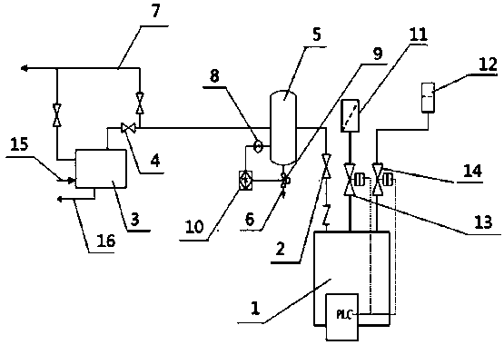
[0020] like figure 1 As shown, the protection and control system of the air compressor includes an air compressor 1, an air compressor outlet valve 2 is arranged on the outlet pipeline at the top of the air compressor 1, and the air compressor outlet valve 2 is connected to the cold dryer through a pipeline 3. Install a cold dryer inlet valve 4 on the pipeline near the cold dryer 3; install a buffer tank 5 near the air compressor outlet valve 2 on the pipeline between the air compressor outlet valve 2 and the cold dryer inlet valve 4, The bottom of the buffer tank 5 is provided with a drainage pipeline 6; the pipeline between the inlet valve 4 of the cold dryer and the buffer tank 5 is also provided with a lead-out line 7 adjacent to the inlet valve 4 of the cold dryer, and the lead-out line 7 is connected to the industrial air pipe network; The outlet pipeline of the cold dryer is connected to the outlet pipeline 7 and connected to the industrial air pipe network together;

...

Embodiment 2

[0023] The protection and control system of the air compressor includes an air compressor 1, an air compressor outlet valve 2 is arranged on the outlet pipeline at the top of the air compressor 1, and the air compressor outlet valve 2 is connected to the cold dryer 3 through a pipeline, and the pipeline A cold dryer inlet valve 4 is installed at the position close to the cold dryer 3; a buffer tank 5 is installed near the air compressor outlet valve 2 on the pipeline between the air compressor outlet valve 2 and the cold dryer inlet valve 4, and the buffer tank 5 The bottom is provided with a drainage pipeline 6; the pipeline between the inlet valve 4 of the cold dryer and the buffer tank 5 is also provided with a lead-out pipeline 7 adjacent to the inlet valve 4 of the cold dryer, and the lead-out pipeline 7 is connected to the industrial air pipe network; The outlet pipeline of the dryer is connected to the outlet pipeline 7 and connected to the industrial air pipe network to...


PUM


Abstract

The invention relates to a protection control system of an air compressor. The protection control system of the air compressor comprises the air compressor; an air compressor outlet valve is arrangedon an outlet pipeline at the top end of the air compressor; the air compressor outlet valve is connected to a freezing dryer through a pipeline; a freezing dryer inlet valve is arranged on the pipeline and near the position of the freezing dryer; a buffer tank is arranged on the pipeline between the air compressor outlet valve and the freezing dryer inlet valve and near the position of the air compressor outlet valve; a water discharging pipeline is arranged at the bottom of the buffer tank; a leading-out pipeline is arranged on the pipeline between the freezing dryer inlet valve and the buffer tank and near the freezing dryer inlet valve; the leading-out pipeline is connected to an industrial air pipe network; an outlet pipeline of the freezing dryer is connected to the leading-out pipeline, and the outlet pipeline of the freezing dryer and the leading-out pipeline are jointly connected to the industrial air pipe network; the protection control system of the air compressor overcomes the defect of no buffer device when the compressed gas in the original air compressor system enters the industrial air pipe network through the freezing dryer; and the buffer tank is arranged at the compressor outlet, so the water of the gas can be discharged out of the buffer tank and the corrosion phenomenon of the outlet pipeline is reduced.

Description

technical field [0001] The invention relates to an improved structure of an air compression protection system, in particular to a protection control system of an air compressor, and belongs to the field of chemical industry. Background technique [0002] The pipeline from the outlet valve of the air compressor to the outlet of the compressor is about 20 meters, and this section of pipeline is made of carbon steel. After the air is compressed by the compressor, the gas at the outlet of the compressor contains some moisture, and the long-term use of the air compressor in this section of the pipeline is severely corroded. Moreover, the compressed gas enters the industrial air pipe network without a buffer device after being cooled by the refrigerated dryer, and the consumption of industrial air users changes sharply, causing the compressor to surge on site, causing great safety hazards to equipment and production. Contents of the invention [0003] In view of the above-menti...

Claims


Application Information

Patent Timeline
Patent Type & Authority Applications(China)
IPC IPC(8): F04B41/02F04B39/16F04B49/10
CPCF04B41/02F04B39/16F04B49/10
Inventor 郝毅
Owner DALIAN FUJIA DAHUA GASOLINEEUM CHEM
Why Eureka
Try Eureka