
Anti-falling rivet structure of backplane

A technology of rivets and back plates, which is applied in the direction of thin plate connection, connection components, electrical equipment structural parts, etc., can solve the problems of easy falling off of rivets, insufficient mechanical strength, and inability to install, so as to improve heat dissipation efficiency, increase heat dissipation area, and enhance The effect of mechanical strength

Pending Publication Date: 2020-02-21
泰洋光电(惠州)有限公司
View PDF0 Cites 0 Cited by
  • Summary
  • Abstract
  • Description
  • Claims
  • Application Information

AI Technical Summary

Problems solved by technology

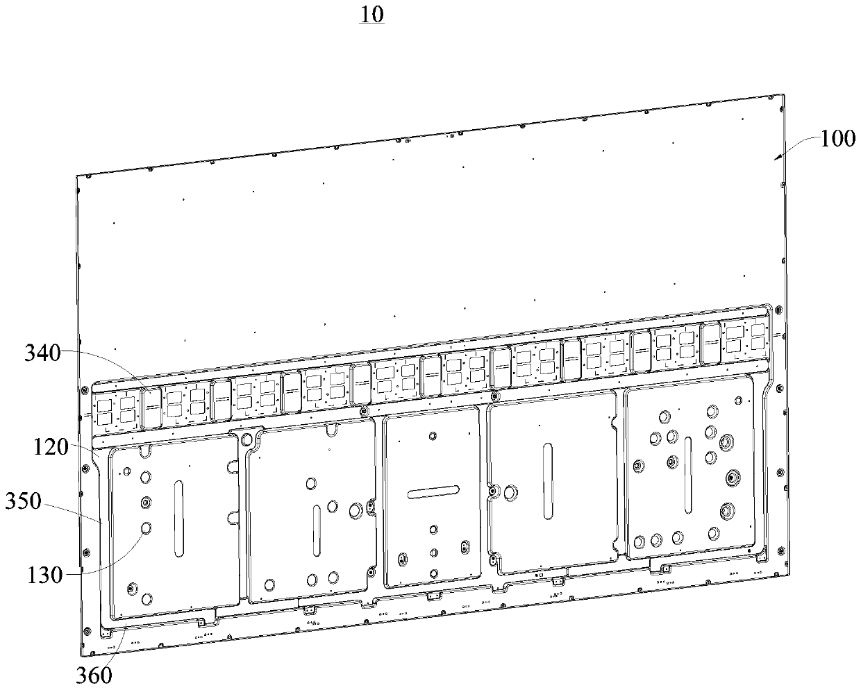
[0003] However, the rivets at this stage are usually assembled on the backplane by riveting, but the mechanical strength of the rivets riveted on the backplane is not enough, so that the rivets are easy to fall off when the backlight module is assembled or when a large external force is applied, resulting in It cannot be installed, which increases the rate of defective products; at the same time, at the current stage, the air circulation at the installation position of the backplane to the backlight module is insufficient and the heat dissipation is uneven, which leads to the heat of the backlight module not being quickly dissipated to the external environment

Method used


Image

  • Anti-falling rivet structure of backplane
  • Anti-falling rivet structure of backplane
  • Anti-falling rivet structure of backplane

Examples


Embodiment Construction

[0030] In order to facilitate the understanding of the present invention, the present invention will be described more fully below with reference to the associated drawings. Preferred embodiments of the invention are shown in the accompanying drawings. However, the present invention can be embodied in many different forms and is not limited to the embodiments described herein. On the contrary, the purpose of providing these embodiments is to make the disclosure of the present invention more thorough and comprehensive.

[0031] It should be noted that when an element is referred to as being “fixed” to another element, it can be directly on the other element or there can also be an intervening element. When an element is referred to as being "connected to" another element, it can be directly connected to the other element or intervening elements may also be present. The terms "vertical," "horizontal," "left," "right," and similar expressions are used herein for purposes of ill...


PUM


Abstract

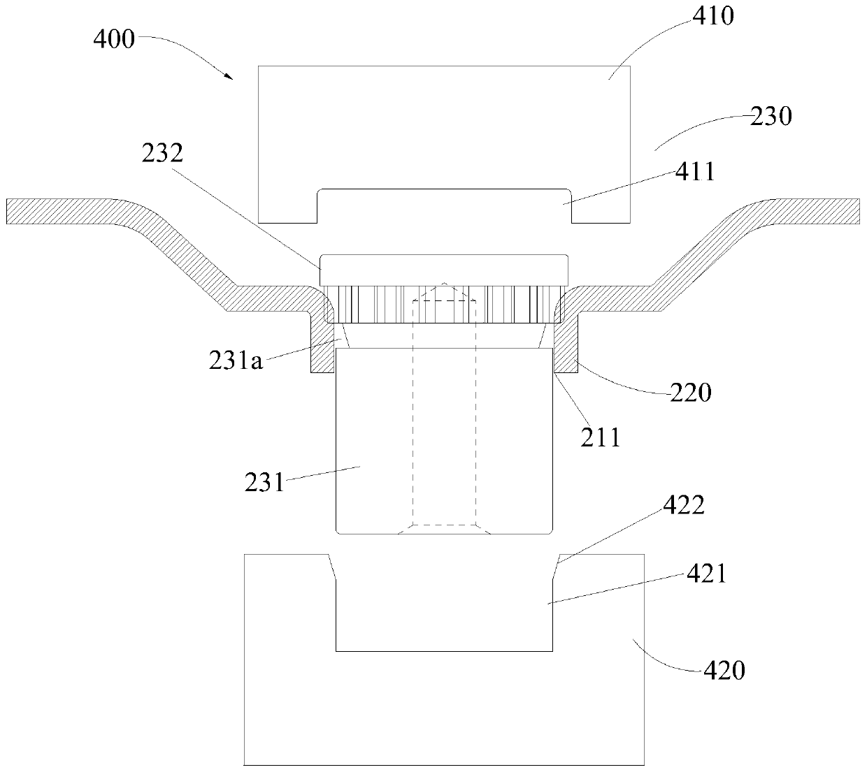
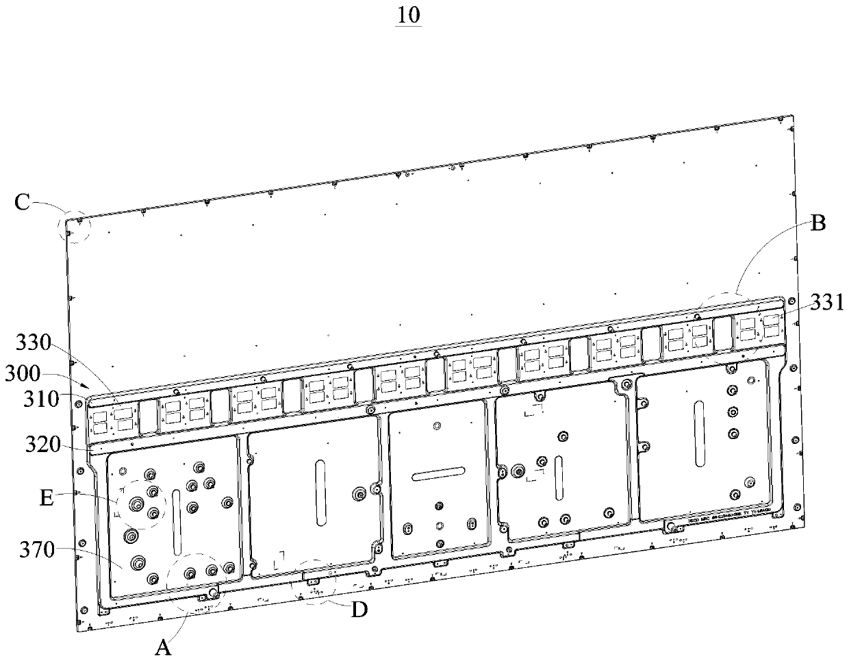
The invention relates to the technical field of backplanes, and discloses an anti-falling rivet structure of a backplane. The anti-falling rivet structure comprises the backplane, a clamping assemblyand a heat dissipation assembly; the clamping assembly comprises convex hulls, bending blocks and riveting components, and the heat dissipation assembly comprises a first heat conducting strip, a second heat conducting strip, a first heat dissipation lug boss and a second heat dissipation lug boss; the backplane is stamped through a mould for forming the convex hulls and the bending blocks, and stamping holes are formed in the convex hulls; then, fastening slots are formed in rivet studs, and the bending blocks are pressed into the fastening slots through the mould, and connected with the fastening slots in a clamping mode; through the above mode, the mechanical strength of the riveting components can be improved, and the riveting components are not prone to affect by larger external forceor fall off during assembly of a backlight module; through formation of a plurality of through holes, ventilation can be improved, and the through holes play a role in heat dissipation; and through arrangement of the first heat conducting strip, the second heat conducting strip, the first heat dissipation lug boss and the second heat dissipation lug boss, the heat dissipation area can be increased, and the heat dissipation efficiency of the backlight module is improved.

Description

technical field [0001] The invention relates to the technical field of backboards, in particular to a structure for preventing rivets from coming off of backboards. Background technique [0002] At present, a rivet is a nail-shaped object used to connect two parts with a through hole and a cap at one end. In riveting, the riveted parts are connected using their own deformation or interference. There are many types of rivets, and they are informal. Commonly used are R-type rivets, fan rivets, blind rivets, tree rivets, semi-round heads, flat heads, semi-hollow rivets, solid rivets, countersunk rivets, blind rivets, hollow rivets, which are usually riveted by using their own deformation connection pieces. Riveting is a mechanical vocabulary, which is a method of using axial force to thicken the nail rod in the rivet hole of the part and form a nail head to connect multiple parts. [0003] However, the rivets at this stage are usually assembled on the backplane by riveting,...

Claims


Application Information

Patent Timeline
Patent Type & Authority Applications(China)
IPC IPC(8): F16B5/04G09F9/00H05K7/20
CPCF16B5/04G09F9/00H05K7/20127H05K7/2039
Inventor 白雷
Owner 泰洋光电(惠州)有限公司
Learn More