
Follow-up high-temperature flammable gas sealing device applied to testing machine

A technology of flammable gas and sealing device, which is applied in the direction of engine sealing, measuring device, mechanical equipment, etc., can solve the problems of low adaptability to working conditions, difficult manufacturing, poor sealing effect, etc., to achieve a wide range of testing and applicable scope Flexible and accurate effects

Pending Publication Date: 2020-02-21
TIANJIN UNIV
View PDF0 Cites 2 Cited by
  • Summary
  • Abstract
  • Description
  • Claims
  • Application Information

AI Technical Summary

Problems solved by technology

However, none of them can realize the sealing of the follow-up mechanical device, and there are disadvantages such as relatively limited application conditions, low adaptability to working conditions, and poor sealing effect.
For example, packing seals are prone to induration under high temperature conditions, and the wear compensation is insufficient; labyrinth seals are non-contact seals, and the sealing effect is far inferior to contact seals; piston ring seals are the most commonly used high-temperature gas seal structures. It must work under continuous lubrication and cooling conditions, and is easy to wear; the brush seal has a long production cycle, is difficult to manufacture, and needs to work under lubrication and cooling conditions
The current sealing methods are not suitable for dynamic sealing of high-temperature flammable gases due to their shortcomings such as low applicability to working conditions and poor sealing effect.

Method used


Image

  • Follow-up high-temperature flammable gas sealing device applied to testing machine
  • Follow-up high-temperature flammable gas sealing device applied to testing machine
  • Follow-up high-temperature flammable gas sealing device applied to testing machine

Examples


Embodiment Construction

[0029] A follow-up type high-temperature flammable gas sealing device applied to a testing machine of the present invention will be described in detail below in conjunction with the embodiments and drawings.

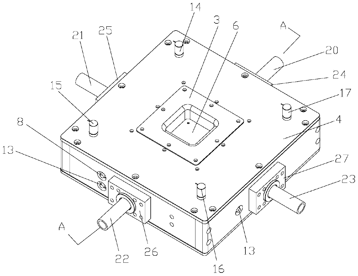
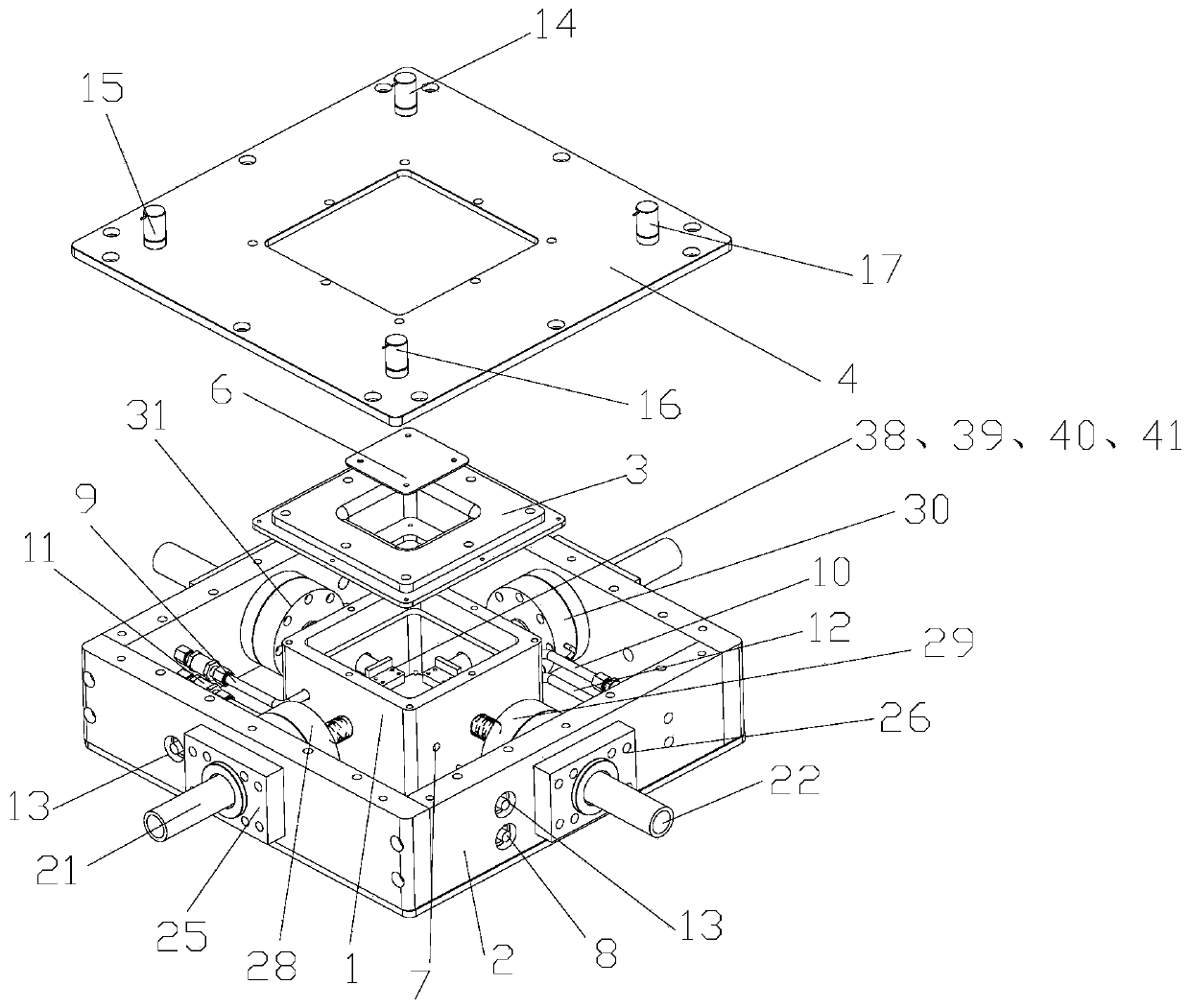
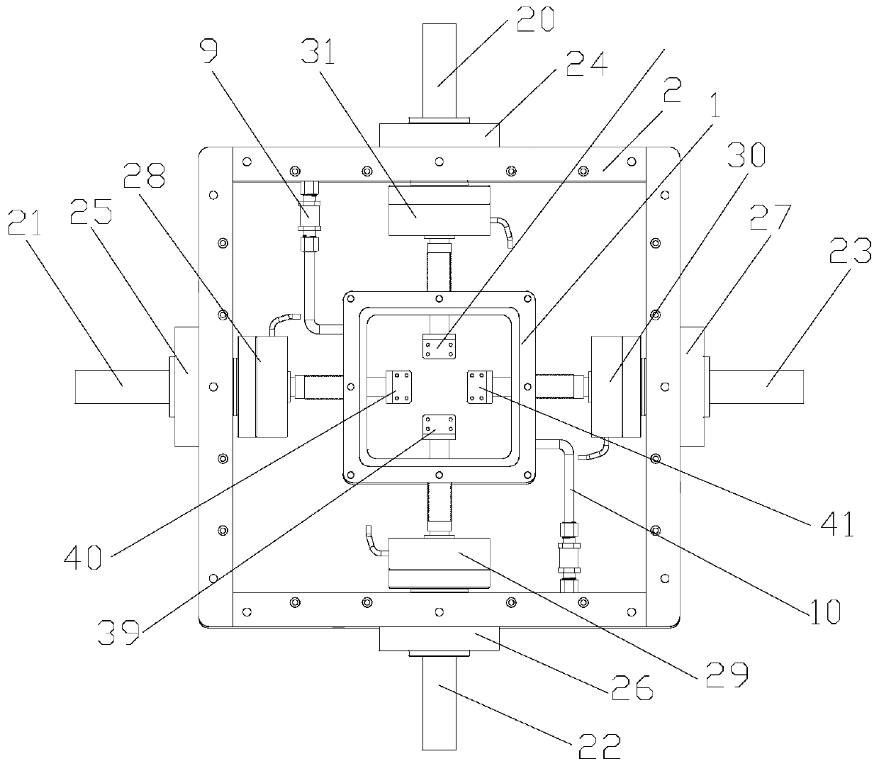
[0030] Such as figure 1 , figure 2 , image 3 , Figure 4 As shown, a follow-up type high-temperature flammable gas sealing device applied to a testing machine of the present invention includes an outer cavity 2 and an inner cavity 1 fixed in the middle of the outer cavity 2, and the inner cavity 1 realizes sealing The key device, the outer cavity body 2 is the inspection of the sealing effect and the secondary protection device, all of which can be made of stainless steel. The four sides of the inner cavity 1 are symmetrically provided with plate fixtures 38, 39, 40, 41 for fixing the workpiece to be measured, the inner cavity 1 is provided with an inner cavity sealing upper cover 3, and the outer cavity The body 2 is provided with a rectangular annular outer cavit...


PUM


Abstract

The invention discloses a follow-up high-temperature flammable gas sealing device applied to a testing machine. Flat plate clamps used for fixing a measured workpiece are arranged on the periphery inan inner cavity. An inner cavity sealing upper cover is arranged on the inner cavity; an outer cavity sealing upper cover is arranged on an outer cavity; the outer periphery of the inner cavity sealing upper cover is fixedly connected with the inner periphery of the outer cavity sealing upper cover through bolts; a ceramic heating sheet is arranged at the outer bottom of the inner cavity; four side surfaces of the inner cavity are provided with load mechanisms used for applying an external force to the measured workpiece. Load driving shafts connected with external power are arranged on the four side faces of the outer cavity. The inner cavity sealing upper cover is provided with an inner cavity visual window, and the inner cavity and the outer cavity are provided with a nitrogen inlet pipe and a flammable gas inlet pipe which are used for introducing nitrogen and flammable gas into the inner cavity, and a mixed gas outlet pipe and a mixed gas collecting pipe which are used for guidingmixed gas in the inner cavity to the outside. The device is suitable for carrying in a high-temperature sealing environment on a mechanical experiment machine.

Description

technical field [0001] The invention relates to a high-temperature flammable gas sealing device. In particular, it relates to a follow-up high-temperature flammable gas sealing device applied to a testing machine. Background technique [0002] In the field of mechanical testing machines, the existing testing machines under normal temperature and pressure cannot meet the requirements of more and more complex working conditions. Many technicians have developed mechanical testing systems for high temperature, high pressure and flammable gas environments. Higher requirements are put forward for dynamic sealing technology. Existing sealing methods mainly include soft and hard packing seals, labyrinth seals, piston ring seals and brush seals. However, the sealing of the follow-up mechanical device cannot be realized, and there are disadvantages such as relatively limited application conditions, low adaptability to working conditions, and poor sealing effect. For example, packin...

Claims


Application Information

Patent Timeline
IPC IPC(8): G01N3/02G01N3/04F16J15/06F16J15/10F16J3/04
CPCG01N3/02G01N3/04F16J15/061F16J15/10F16J3/04G01N2203/0226G01N2203/0236
Inventor 陈刚冯少武林强王晓涵
Owner TIANJIN UNIV
Learn More