Compressor machine

A compressor and machine technology, applied in the field of compressor machines, can solve problems affecting the thermal dynamic efficiency of compressor machines, and achieve the effect of improving efficiency

Pending Publication Date: 2020-02-21
ROBERT BOSCH GMBH
View PDF8 Cites 0 Cited by
  • Summary
  • Abstract
  • Description
  • Claims
  • Application Information

AI Technical Summary

Problems solved by technology

The size of the gap size influences the leakage, the effective cross-section and the losses due to the vortex, so that it affects the thermodynamic efficiency of the compressor machine

Method used


Image

  • Compressor machine
  • Compressor machine

Examples


Embodiment Construction

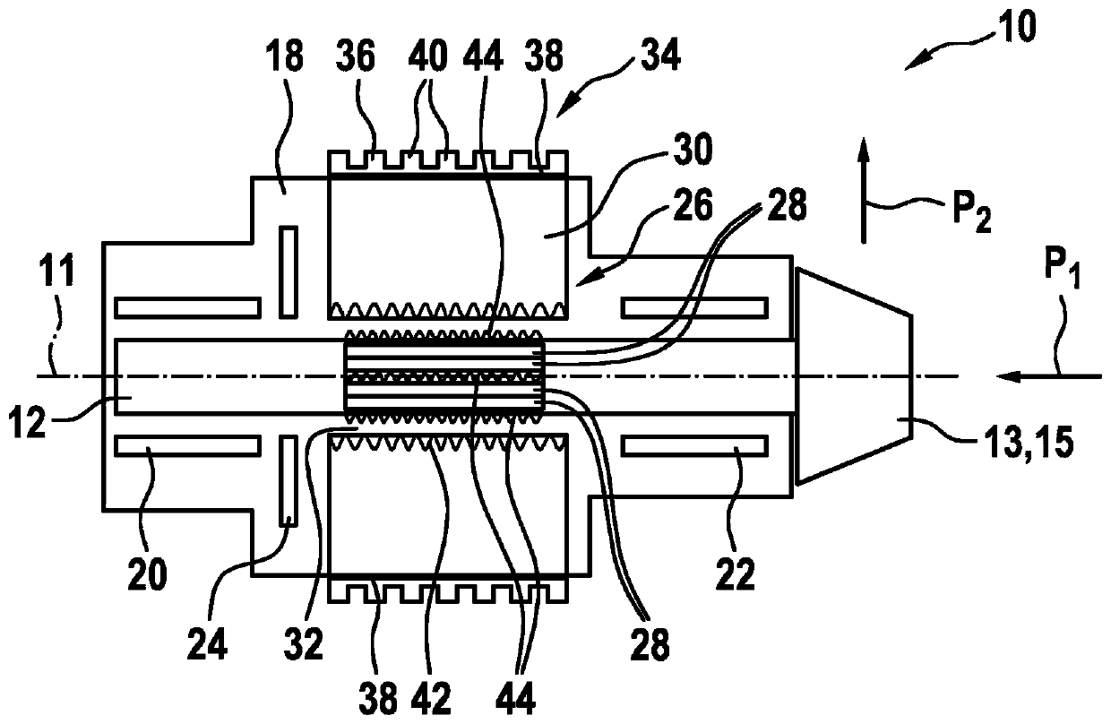
[0019] figure 1 A first compressor machine 10 is shown very schematically. The compressor machine 10 is used for compressing gas and for this purpose has a shaft 12 mounted rotatably about a longitudinal axis 11 , which is connected at one end in a rotationally fixed manner to a compressor stage 15 with an impeller 13 . The compressor stage 15 or impeller 13 is configured as a flow device to increase the gas supplied to or sucked by the impeller 13 from a first pressure p1 to a second pressure p2, which is greater than the first pressure p2. pressure p1. The compressor machine 10 or the compressor arrangement also has a housing 18 shown only in area, in which the shaft 12 is arranged at least in area. The housing 18 is also used to arrange two radial bearings 20, 22 and an axial bearing 24, wherein the bearings are configured as dynamic pressure air bearings or static pressure air bearings, that is, the bearings use gas or air as the shaft 12 and the corresponding Work in t...


PUM


Abstract

The invention relates to a compressor machine (10; 10a), in particular a generator or a compressor unit for compressing a gas, comprising a shaft (12) which is arranged in a housing (18) so as to be able to rotate about a longitudinal axis (11) and which is mounted in at least two radial bearings (20, 22) and a thrust bearing (24), the radial bearings (20, 22) and/or the thrust bearing (24) beingin the form of an aerodynamic or aerostatic bearing, the shaft (12) being at least indirectly connected to a compressor stage (15) or driving stage comprising an impeller wheel (13).

Description

technical field [0001] The invention relates to a compressor machine according to the preamble of claim 1 . Background technique [0002] Such compressor machines are known from the prior art and are used, for example, as compressors for compressing air or gas. In this case, the shaft of the compressor machine is supported in the housing in at least two radial bearings and one axial bearing. The shaft is connected to the impeller, which is driven or rotated by the shaft in the case of a compressor, and which is operatively connected by the flowing gas in the case of a generator, so that the impeller drives the shaft to generate an electric current . [0003] Furthermore, it is generally known that the efficiency of such compressor machines depends on the size of the radial and axial gap dimensions. The size of the gap size influences the leakage, the effective cross-section and the losses caused by the swirl, so that the thermodynamic efficiency of the compressor machine ...

Claims


Application Information

Patent Timeline
Patent Type & Authority Applications(China)
IPC IPC(8): F04D25/06F04D29/051F04D29/053F04D29/057F04D29/58
CPCF04D25/06F04D29/0513F04D29/053F04D29/057F04D29/5806F05D2260/22141F05D2260/205F01D25/22F05D2260/2212F05D2240/53F04D25/0606F04D29/58F04D25/062H02K9/00
Inventor T·拉霍S·德尔哈尔特
Owner ROBERT BOSCH GMBH
Why Eureka
Try Eureka