Magnetic shoe continuous feeding automatic chamfering machine

A technology of chamfering machine and magnetic tile, applied in the field of chamfering machine, can solve the problems of damage to chamfering equipment, increase energy consumption, high noise, etc., and achieve the effects of low equipment failure rate, high safety performance, and reduced energy consumption

Inactive Publication Date: 2020-02-25
HUNAN AEROSPACE MAGNET & MAGNETO
View PDF12 Cites 2 Cited by
  • Summary
  • Abstract
  • Description
  • Claims
  • Application Information

AI Technical Summary

Problems solved by technology

The existing chamfering equipment adopts the reciprocating action of the heavy hammer chain transmission mechanism, which transmits the product to the grinding wheel for chamfering operation, and the chain drives the heavy hammer to push. When the heavy hammer falls by gravity, there is no fixed guide, the structure is unstable and The noise is high, and it is easy to shift the positioning position of the product, resulting in inaccurate chamfering position of the product, resulting in defective products; at the same time, due to the high instantaneous force of the heavy hammer falling, it is easy to damage the chamfering equipment, which increases the equipment failure rate and maintenance. cost, and the chain transmission method is prone to chain breakage, which has certain safety hazards; every time it moves, it must drive the weight to move up and down, increasing energy consumption

Method used


Image

  • Magnetic shoe continuous feeding automatic chamfering machine
  • Magnetic shoe continuous feeding automatic chamfering machine
  • Magnetic shoe continuous feeding automatic chamfering machine

Examples


Embodiment Construction

[0022] The present invention will be further described in detail below in conjunction with the accompanying drawings and specific embodiments.

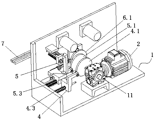
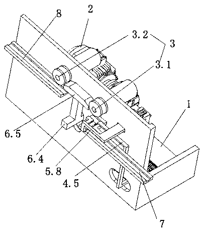
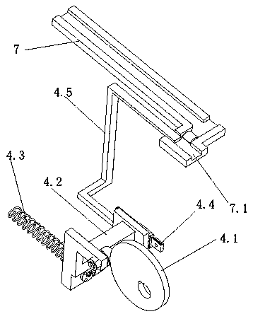
[0023] like figure 1 As shown, the magnetic tile continuous feeding automatic chamfering machine in this embodiment includes a working frame 1, a transmission motor 2, a grinding wheel 3, a first linkage device 4 for controlling the movement of the magnetic tile along the X-axis direction, and a first linkage device 4 for controlling the movement of the magnetic tile. The second linkage device 5 for moving the tile along the Y-axis direction and the third linkage device 6 for controlling the movement of the magnetic tile along the Z-axis direction, the transmission motor 2 is placed on the bottom plate of the work frame 1, and the grinding wheel 3 Fixed on the back plate of the working frame 1 , the first linkage device 4 , the second linkage device 5 and the third linkage device 6 are connected to the transmission motor 2 .

[0024]...


PUM


Abstract

The invention relates to a magnetic shoe continuous feeding automatic chamfering machine, which includes a working frame, a transmission motor, a grinding wheel, a first linkage device for controllingmovement of magnetic shoes in the X-axis direction, a second linkage device for controlling movement of the magnetic shoes in the Y-axis direction, and a third linkage device for controlling movementof the magnetic shoes in the Z-axis direction. The transmission motor is placed on a bottom plate of the working frame, the grinding wheel is fixed to a back plate of the working frame, and the firstlinkage device, the second linkage device and the third linkage device are connected with the transmission motor. The effects of continuous feeding, accurate control and accurate positioning of ferrite magnetic shoes can be achieved by using the magnetic shoe continuous feeding automatic chamfering machine, and the safety in the magnetic shoe chamfering process is ensured.

Description

technical field [0001] The invention relates to the technical field of chamfering machines, in particular to an automatic chamfering machine with continuous feeding of magnetic tiles. Background technique [0002] In the ferrite magnetic tile manufacturing industry, it is often necessary to chamfer the outer end face of the magnetic tile. The existing chamfering equipment adopts the reciprocating action of the heavy hammer chain transmission mechanism, which transmits the product to the grinding wheel for chamfering operation, and the chain drives the heavy hammer to push. When the heavy hammer falls by gravity, there is no fixed guide, the structure is unstable and The noise is high, and it is easy to shift the positioning position of the product, resulting in inaccurate chamfering position of the product, resulting in defective products; at the same time, due to the high instantaneous force of the heavy hammer falling, it is easy to damage the chamfering equipment, which i...

Claims


Application Information

Patent Timeline
Patent Type & Authority Applications(China)
IPC IPC(8): B24B9/06B24B27/00B24B41/00B24B55/00B24B41/06B24B41/02
CPCB24B9/06B24B27/0076B24B41/005B24B41/02B24B41/06B24B55/00
Inventor 寇清舒书胡盛青黄小琴
Owner HUNAN AEROSPACE MAGNET & MAGNETO
Why Eureka
Try Eureka