Sludge treatment device for rapid dehydration

A sludge treatment and rapid dehydration technology, which is applied in sludge treatment, water/sludge/sewage treatment, chemical instruments and methods, etc., can solve problems such as low efficiency, single dehydration method, and inability to separate sludge moisture. Achieve the effect of improving dehydration efficiency, good drainage effect and good dehydration effect

Inactive Publication Date: 2020-02-25
周其胤
0 Cites 4 Cited by

AI-Extracted Technical Summary

Problems solved by technology

[0002] Sludge treatment is the process of reducing, stabilizing and harmless sludge such as concentration, tempering, dehydration, stabilization, drying or incineration. In sludge treatment, and in the process of sludge treatment, it is necessary to Dewatering th...

Method used

In the present embodiment, described the 3rd filter plate 19 is vertically set, and described 3rd filter plate 19 is provided with a plurality of pieces, the bottom of multiple described 3rd filter plate 19 is inclined to be set, and it is convenient to set in inclination The sludge falls, and through multi-layer set...

Abstract

The invention discloses a sludge treatment device for rapid dehydration, which includes a feeding mechanism, a dehydration mechanism, a drainage mechanism, and a discharging mechanism, wherein the feeding mechanism includes a feeding chamber; the feeding chamber is provided with a feeding cavity inside; the dehydration mechanism includes a dehydration chamber; a first filter plate is provided at ajunction between the dehydration chamber and the feeding cavity; second filter plates are obliquely disposed at an end of the dehydration chamber near the feeding cavity; a middle portion of the dehydration chamber is provided with a squeezing cavity; the other end of the dehydration chamber is provided with a third filter plate; the drainage mechanism includes a drainage channel; the drainage channel is disposed at the bottom of the dehydration chamber; the discharging mechanism includes a discharging pipe. According to the device, through a plurality of the inclined second filter plates, water in the sludge is allowed to pass through multiple layers of filtration to achieve the purpose of multi-layer filtration and drainage, and through up-down movement for repeated squeezing of squeezing plates, the purpose of drainage and the purpose of multiple drainage are achieved, the purpose of rapid dehydration is achieved, and the efficiency is high.

Application Domain

Sludge treatment

Technology Topic

SludgeFiltration +2

Image

  • Sludge treatment device for rapid dehydration
  • Sludge treatment device for rapid dehydration
  • Sludge treatment device for rapid dehydration

Examples

  • Experimental program(1)

Example Embodiment

[0020] The technical solutions in the embodiments of the present invention will be clearly and completely described below in conjunction with the accompanying drawings in the embodiments of the present invention. Obviously, the described embodiments are only a part of the embodiments of the present invention, rather than all the embodiments. Based on the embodiments of the present invention, all other embodiments obtained by those of ordinary skill in the art without creative work shall fall within the protection scope of the present invention.
[0021] In the description of the present invention, it should be noted that the directions or positional relationships indicated by the terms "vertical", "upper", "lower", "horizontal" and the like are based on the directions or positional relationships shown in the drawings, and are only for It is convenient to describe and simplify the description of the present invention, rather than indicating or implying that the pointed device or element must have a specific orientation, be constructed and operated in a specific orientation, and therefore cannot be understood as a limitation of the present invention.
[0022] In the description of the present invention, it should also be noted that the terms "set", "installation", "connected", and "connected" should be interpreted broadly unless otherwise clearly defined and restricted. For example, it can be a fixed connection or a fixed connection. It can be a detachable connection, or an integral connection, a mechanical connection, an electrical connection, a direct connection, or a connection through an intermediate medium, or a communication between two components. For those of ordinary skill in the art, the specific meaning of the above-mentioned terms in the present invention can be understood according to specific circumstances.
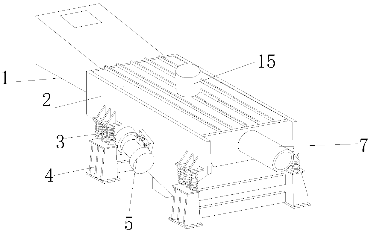
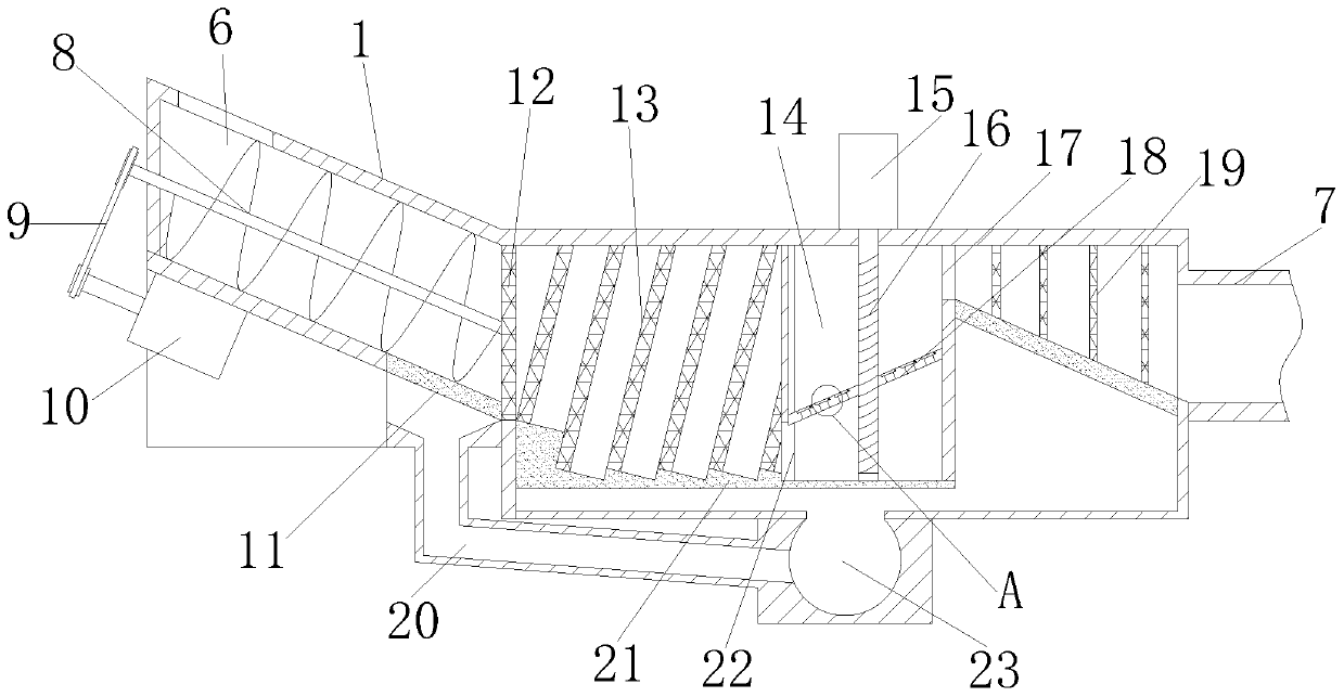
[0023] Such as Figure 1-3 As shown, a rapid dehydration sludge treatment device includes a feeding mechanism, a dehydration mechanism, a drainage mechanism, and a discharging mechanism; the feeding mechanism includes a feeding chamber 1 in which a feeding Chamber 6; the dehydration mechanism includes a dehydration chamber 2, the inner cavity of the dehydration chamber 2 is communicated with the feed chamber 6, the connection between the dehydration chamber 2 and the feed chamber 6 is provided with a first filter plate 12, so The dewatering chamber 2 is provided with a second filter plate 13 obliquely at one end close to the feeding chamber 6, a squeezing cavity 14 is provided in the middle of the dewatering chamber 2, and a squeezing plate 18 is slidably connected to the squeezing chamber 14 The squeeze plate 18 is provided with a reciprocating mechanism, and the other end of the dehydration chamber 2 is provided with a third filter plate 19; the drainage mechanism includes a drainage channel 23 which is provided at the bottom of the dehydration chamber 2 and is connected to The inner cavity of the dewatering chamber 2 is connected; the discharging mechanism includes a discharging pipe 7, and the discharging pipe 7 communicates with the side of the dewatering chamber 2 close to the third filter plate 19. When in use, the sludge is thrown into In the feeding chamber, the sludge enters the dehydration chamber through the feeding chamber, and the water in the sludge enters the dehydration chamber through the first filter plate through the first filter plate, and falls into the drainage channel set at the bottom for discharge , And through the installation of multiple inclined second filter plates, the water in the sludge is filtered through multiple layers, and discharged into the drainage channel first, and the water at the bottom of the sludge is gradually discharged into the bottom drainage channel to achieve multiple layers The purpose of filtering and draining water is good, and through the set squeezing cavity, the squeeze plate is repeatedly squeezed through the up and down movement to achieve the purpose of drainage, and the third filter plate is set to filter and drain again to achieve multiple drainage. Purpose, convenient and fast to complete the purpose of dehydration, high efficiency.
[0024] In this embodiment, a vibration motor 5 is installed on the outside of the dewatering chamber 2, and a support frame 4 is connected to both sides of the dewatering chamber 2 through a shock-absorbing spring 3. The vibration motor can control the moisture in the sludge in the dewatering chamber. Fast separation and improve dehydration efficiency.
[0025] In this embodiment, a screw conveying rod 8 is rotatably connected in the feeding chamber 1, and one end of the screw conveying rod 8 is connected to a first driving motor 10 through a belt 9, and the screw conveying rod is driven to rotate by the first driving motor. And realize the purpose of sludge transportation.
[0026] In this embodiment, the bottom of the feeding chamber 1 is provided with a first filter membrane 11, and the bottom of the first filter membrane 11 is connected to the drainage channel 23 through a pipe 20, and the sludge is transported to the second through a bolt conveying rod. A filter plate is squeezed with the first filter plate, and the water is squeezed out and discharged into the drainage channel through the first filter membrane.
[0027] In this embodiment, the reciprocating mechanism includes a second drive motor 15. The rotation shaft of the second drive motor 15 is connected with a screw 16 which is rotatably connected with the extrusion plate 18, and the screw is driven by the second drive motor. Rotate and make the squeezing plate move up and down to achieve the purpose of squeezing and dewatering the sludge.
[0028] In this embodiment, an inlet 22 is opened at the bottom of the extrusion cavity 14 on the side close to the second filter plate 13, and an outlet 17 is opened at the upper end of the extrusion cavity 14 on the side close to the third filter plate 19. By moving the squeeze plate up and down, the sludge enters through the inlet and is discharged through the outlet.
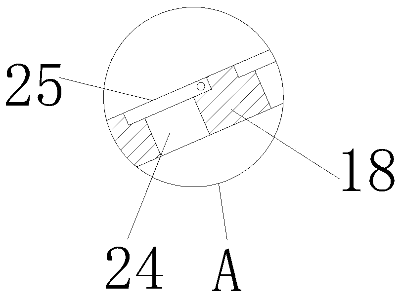
[0029] In this embodiment, the squeeze plate 18 is inclined, the squeeze plate 18 is provided with a through groove 24, and the upper end of the through groove 24 is rotated to be provided with a one-way baffle 25 to realize the upward transportation of sludge. The purpose is to transport to the third filter plate through the outlet.
[0030] In this embodiment, the third filter plate 19 is arranged vertically, and there are multiple third filter plates 19, and the bottoms of the third filter plates 19 are inclined to facilitate the sludge falling. , And through the multi-layer setting, the water in the sludge can be filtered, separated and discharged to facilitate dehydration.
[0031] In this embodiment, a second filter membrane 21 is provided at the bottom of the inner cavity of the dehydration chamber 2 to facilitate the drainage of water and prevent the entry of sludge.

PUM

no PUM

Description & Claims & Application Information

We can also present the details of the Description, Claims and Application information to help users get a comprehensive understanding of the technical details of the patent, such as background art, summary of invention, brief description of drawings, description of embodiments, and other original content. On the other hand, users can also determine the specific scope of protection of the technology through the list of claims; as well as understand the changes in the life cycle of the technology with the presentation of the patent timeline. Login to view more.

Similar technology patents

CCM for fuel cell and preparation method thereof

PendingCN114520339AGood drainageGood durability against degradation and loss
Owner:ZHEJIANG TIANNENG HYDROGEN ENERGY TECH CO LTD

Screw extrusion dehydrator

PendingCN110345720AImprove extrusion efficiencyGood drainage
Owner:SHENYANG YUANDA TECH IND

Invisible fire fighting passage and laying method thereof

PendingCN106930169Aincrease green areagood drainage
Owner:广西蓝天科技股份有限公司

Air energy firewood stove

ActiveCN107238112AGood drainagereduce heat loss
Owner:夏国强

Water discharging system for water purifier

PendingCN109928558AGood drainageSimplify drainage operation
Owner:深圳市优悦环保科技有限公司

Classification and recommendation of technical efficacy words

  • Improve efficiency
  • Good drainage

System plugging and draining structure for tunnel leakage treatment

InactiveCN105484773AClear drainage pathGood drainage
Owner:WUHAN MUNICIPAL ENG DESIGN & RES INST

Window type air conditioner

ActiveCN106403063ASimple structureGood drainage
Owner:GD MIDEA AIR-CONDITIONING EQUIP CO LTD

Oil tank and motorcycle thereof

ActiveCN104276236AGood drainageEnsure cleanliness
Owner:CHONGQING LONCIN MOTOR

Bamboo rat feeding device for smart livestock breeding

ActiveCN109819900Agood drainageNot easy to pollute
Owner:李蕾
Why Eureka
Try Eureka