Liftable mobile ladder stand and working method thereof

A lifting and climbing technology, applied in the direction of ladders, buildings, building structures, etc., can solve the problems of poor stability, labor-intensive, no operation platform, etc., and achieve the effect of ensuring stability

Inactive Publication Date: 2020-02-25
XUZHOU MALONG ENERGY SAVING ENVIRONMENTAL PROTECTION EQUIP
View PDF5 Cites 0 Cited by
  • Summary
  • Abstract
  • Description
  • Claims
  • Application Information

AI Technical Summary

Problems solved by technology

[0003] 1. The straight ladder needs to be moved every time, which consumes manpower and is inconvenient to move;
[0004] 2. The straight ladder leans against the outer wall of the cylinder and requires workers to support it, and the stability is relatively poor;
[0005] 3. There is no operating platform, which is not convenient for workers to operate the welding machine;
[0006] 4. When welding the outer ring weld of the cylinder, the straight ladder cannot follow the rotation of the cylinder;
[0007] 5. The height of the straight ladder does not match the diameter of the cylinder, and it is inconvenient to go up and down the cylinder

Method used


Image

  • Liftable mobile ladder stand and working method thereof
  • Liftable mobile ladder stand and working method thereof

Examples


Embodiment 1

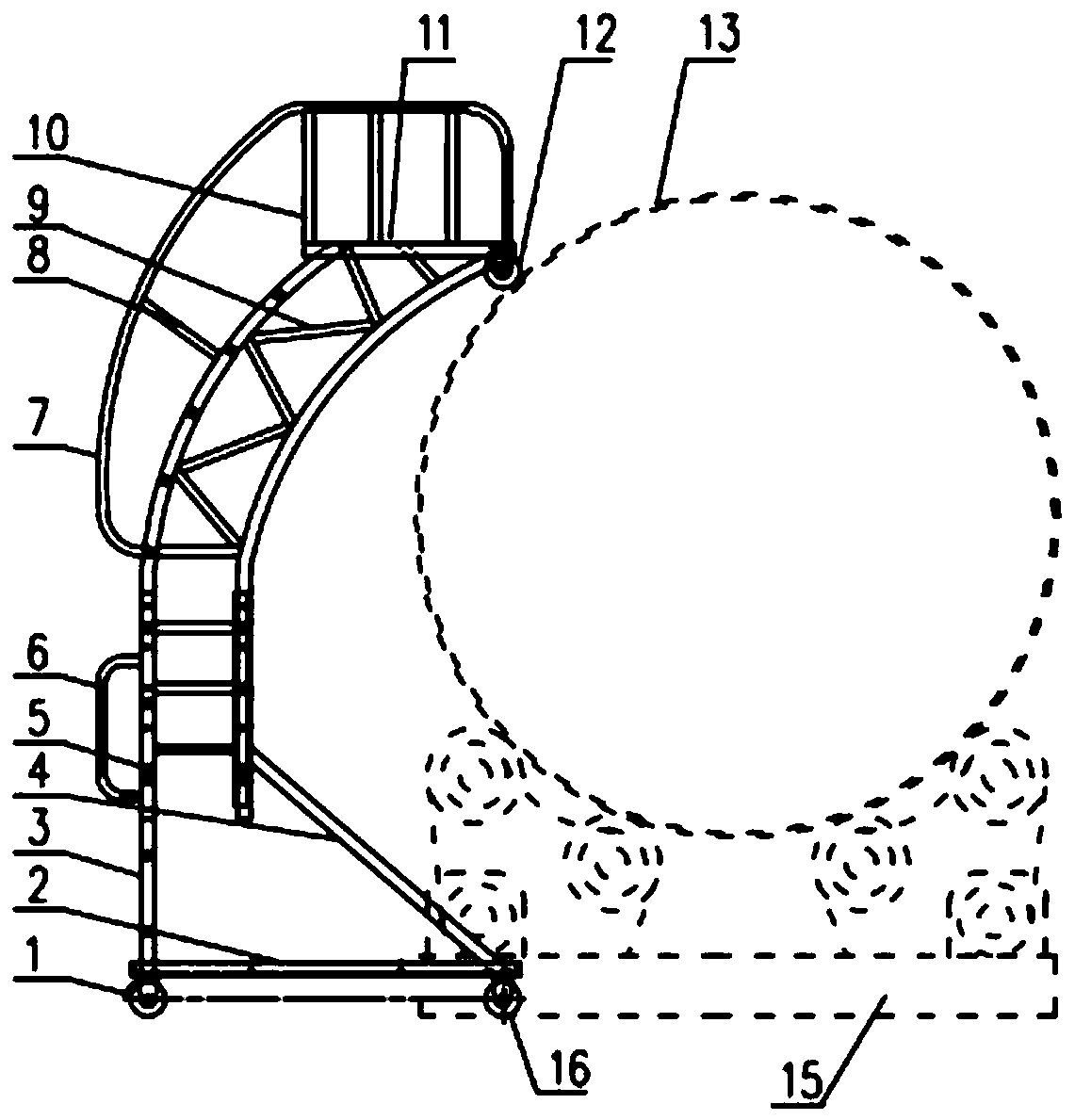
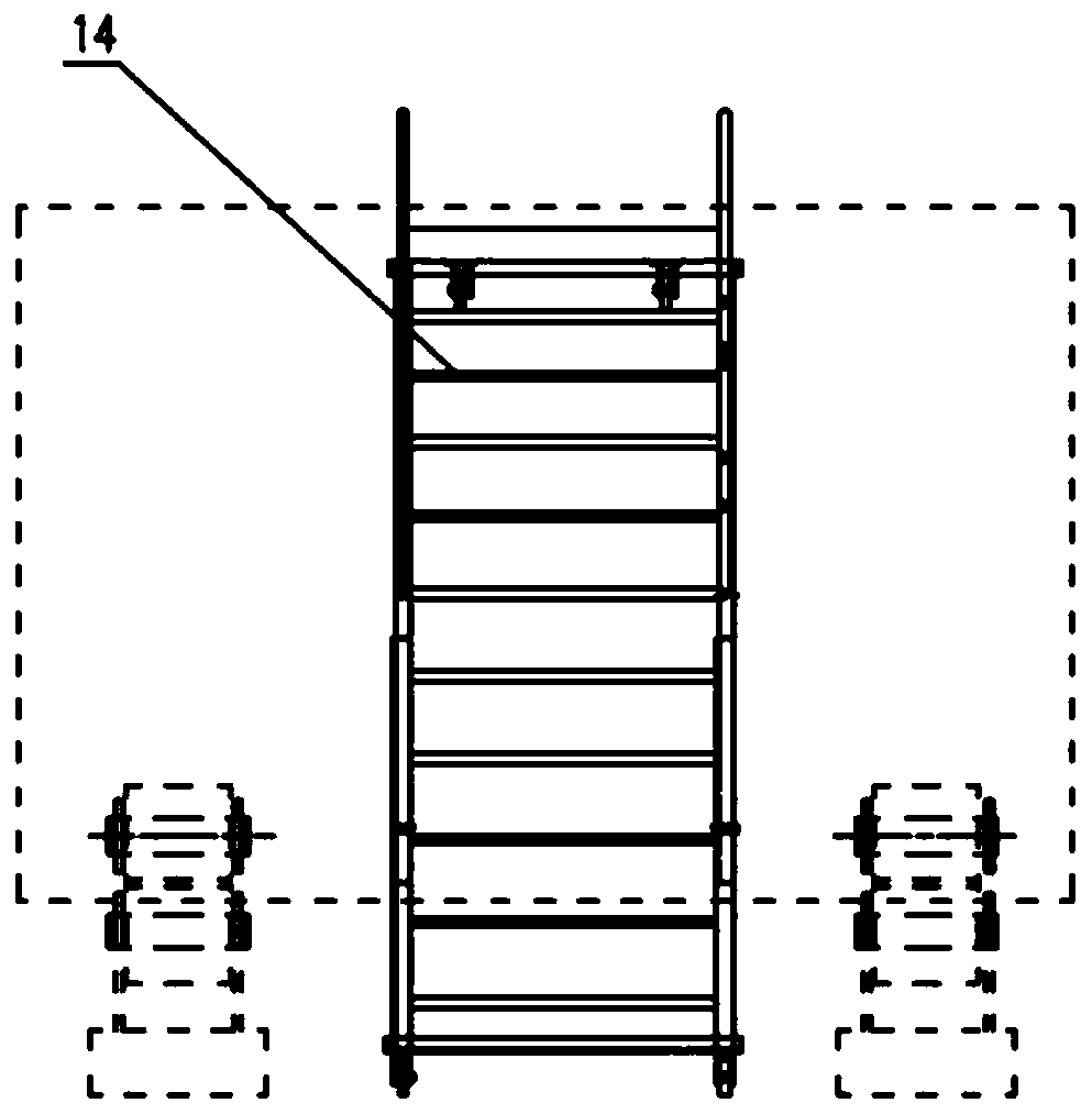
[0027] Such as Figure 1 to Figure 2 As shown, the present embodiment 1 provides a liftable mobile climbing ladder, comprising: a lower ladder part and an arc-shaped upper ladder part; a sliding wheel 12 is provided on the top side of the upper ladder part; the sliding wheel 12 It is suitable for abutting against the outer wall of a cylinder to be welded 13; and the upper ladder part is connected with the lower ladder part through a height adjustment assembly.

[0028] Specifically, the liftable mobile ladder of this embodiment facilitates approaching the outer wall of the cylinder 13 to be welded through the arc-shaped upper ladder, and realizes effective contact with the outer wall of the cylinder 13 to be welded through the sliding wheel 12, the sliding wheel 12 It can rotate following the rotation of the cylinder 13 to ensure the stability of welding; in addition, the liftable mobile ladder can also adjust the installation height of the upper ladder through the height adju...

Embodiment 2

[0045] On the basis of embodiment 1, this embodiment 2 provides a working method of a liftable mobile ladder, including: pressing against the outer wall of a cylinder to be welded by a sliding wheel arranged on the top side of the upper ladder part; And the installation height of the upper ladder part installed on the lower ladder part is adjusted by the height adjustment assembly.

[0046] Specifically, for the specific structure and working principle of the liftable mobile ladder in this embodiment, refer to the description in Embodiment 1, which will not be repeated here.

[0047] In summary, the liftable mobile ladder of the present application facilitates access to the outer wall of the cylinder to be welded through the arc-shaped upper ladder, and realizes effective contact with the outer wall of the cylinder to be welded through the sliding wheels, which can follow the cylinder The rotation of the body rotates to ensure the stability of the welding; in addition, the lif...


PUM


Abstract

The invention relates to the field of machining, in particular to a liftable mobile ladder stand and a working method thereof. The liftable mobile ladder stand comprises a lower ladder part and an arc-shaped upper ladder part; one side of the top of the upper ladder part is provided with a sliding wheel, and the sliding wheel is suitable for abutting against the outer wall of a to-be-welded barrelbody; and the upper ladder part and the lower ladder part are connected through a height adjusting assembly. The liftable mobile ladder stand can get close to the outer wall of the to-be-welded barrel body conveniently through the arc-shaped upper ladder part and make effective contact with the outer wall of the to-be-welded barrel body through the sliding wheel, the sliding wheel can rotate along with rotation of the barrel body, and accordingly, the welding stability is ensured. In addition, the installation height of the upper ladder part of the liftable mobile ladder stand can be adjustedthrough the height adjusting assembly, so that the welding requirements of barrel bodies different in diameter can be met.

Description

technical field [0001] The invention belongs to the field of mechanical processing, and in particular relates to a liftable mobile ladder and a working method thereof. Background technique [0002] When welding the outer wall of a circular cylinder, workers need to operate the welding machine on the upper part of the outer surface of the cylinder. The cylinder is rotated and welded on the turning platform following the turning platform. The workers go up and down the cylinder, and the operation of the welding machine adopts a conventional straight ladder. shortcoming: [0003] 1. The straight ladder needs to be moved every time, which consumes manpower and is inconvenient to move; [0004] 2. The straight ladder leans against the outer wall of the cylinder and requires workers to support it, and the stability is relatively poor; [0005] 3. There is no operating platform, which is not convenient for workers to operate the welding machine; [0006] 4. When welding the oute...

Claims


Application Information

Patent Timeline
IPC IPC(8): E06C1/30E06C1/397E06C7/18E06C7/06E06C7/08
CPCE06C1/30E06C1/397E06C7/06E06C7/08E06C7/182E06C7/183
Inventor 王道辉马恋
Owner XUZHOU MALONG ENERGY SAVING ENVIRONMENTAL PROTECTION EQUIP
Why Eureka
Try Eureka