
Asymmetric type centrifugal impeller fan

A centrifugal impeller, asymmetric technology, used in non-variable-capacity pumps, mechanical equipment, machines/engines, etc., can solve the problem of loud fan noise, reduce noise, improve installation and positioning accuracy, and reduce rotational noise.

Pending Publication Date: 2020-02-25
HUNAN LIANCHENG TRACK EQUIP CO LTD
View PDF0 Cites 1 Cited by
  • Summary
  • Abstract
  • Description
  • Claims
  • Application Information

AI Technical Summary

Problems solved by technology

[0004] The purpose of the present invention is to provide an asymmetric centrifugal impeller fan to solve the problem of high noise in the cooling process of the fan

Method used


Image

  • Asymmetric type centrifugal impeller fan
  • Asymmetric type centrifugal impeller fan
  • Asymmetric type centrifugal impeller fan

Examples


Embodiment Construction

[0033] The embodiments of the present invention will be described in detail below with reference to the accompanying drawings, but the present invention can be implemented in various ways defined and covered by the claims.

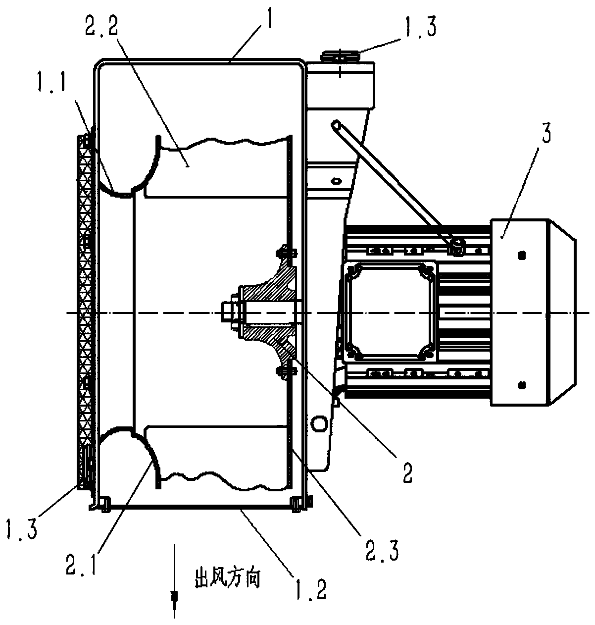
[0034] see Figure 1 to Figure 5 , an asymmetric centrifugal impeller fan, this embodiment is applied to the cooling and heat dissipation of locomotive traction transformers.

[0035] An asymmetric centrifugal impeller fan includes a casing 1, an impeller 2 and a motor 3; the impeller 2 is installed in the casing 1 and connected with the output shaft of the motor 3 to realize the rotation of the impeller 2;

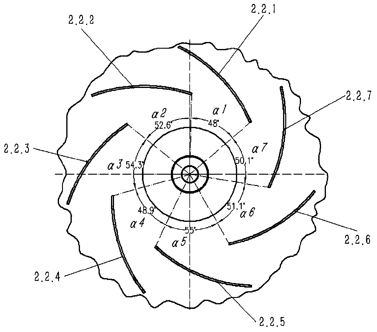
[0036] The impeller 2 includes a front disc 2.1, a blade 2.2 and a rear disc 2.3 connected sequentially along the axial direction of the impeller 2; see figure 1 and image 3 , the edge contour line of the free end of the blade 2.2 is an irregular curve, and the irregular curve is composed of arcs with different curvature radii, so as to avoid the a...


PUM


Abstract

The invention provides an asymmetric type centrifugal impeller fan comprising a shell, an impeller and a motor. The impeller is installed in the shell and is connected with a motor output shaft so asto achieve rotation of the impeller. The impeller comprises a front wheel disc, a blade and a rear wheel disc which are connected sequentially in the axial direction of the impeller. The edge contourline of the end of the free end of the blade is an irregular curve for lowering rotation noise of the fan. The edge contour line of the end of the free end of the blade of the impeller is arranged tobe the irregular curve, thus when the impeller rotates, airflow forms different pulsed excitation at the end of the free end of the single blade, concentration frequency band noise generated due to single pulsed excitation superposition generated at the end of the free end of the blade is avoided, and the noise of the asymmetric type centrifugal impeller fan is lowered by about 5 dB compared withthe noise of a fan adopting a symmetrical type impeller of the same aerodynamic performance.

Description

technical field [0001] The invention relates to the technical field of transformer cooling and heat dissipation, in particular to an asymmetric centrifugal impeller fan. Background technique [0002] China's railways are developing by leaps and bounds. High-speed EMUs have spread all over the country, and people's travel methods have become more convenient and faster. In order to ensure people's riding comfort and reduce the damage of locomotives and vehicles to the environment along the line, EMUs have stricter requirements on noise and vibration, and even put forward higher control requirements according to different environmental conditions when EMUs are running at high speed, starting and stopping . The traction transformer needs to be cooled on the EMU. The cooling device takes away a large amount of heat generated by the traction transformer to ensure the normal operation of the equipment, thereby ensuring the driving safety of the EMU. The cooling device of the tra...

Claims


Application Information

Patent Timeline
Patent Type & Authority Applications(China)
IPC IPC(8): F04D25/08F04D29/28F04D29/30F04D29/66F04D29/62F04D29/42F04D29/08H01F27/08
CPCF04D25/08F04D29/083F04D29/281F04D29/30F04D29/4213F04D29/4226F04D29/624F04D29/663F04D29/666F04D29/668H01F27/085
Inventor 刘梦安屈小章张加贝詹腾翟方志
Owner HUNAN LIANCHENG TRACK EQUIP CO LTD
Learn More