A ship attitude dynamic simulation system for wind tunnel test and its working method

A technology of wind tunnel test and dynamic simulation, which is applied in the field of wind tunnel test, can solve the problems that the blockage of wind tunnel flow field is difficult to meet the experimental standard, the effect of motion simulation is poor, and the volume of the device is large, so as to enrich the content of dynamic wind tunnel test, Ease of installation and commissioning, less system components

Active Publication Date: 2021-06-15
NANJING UNIV OF AERONAUTICS & ASTRONAUTICS
View PDF8 Cites 0 Cited by
  • Summary
  • Abstract
  • Description
  • Claims
  • Application Information

AI Technical Summary

Problems solved by technology

[0005] Most of the existing ship wind tunnel test attitude angle simulation devices require multiple sets of hydraulic systems to be linked. The entire device is bulky and is generally installed under the aviation floor in the wind tunnel, which makes it difficult to achieve the blockage degree of the wind tunnel flow field. The experimental standard has a great influence on the experimental results and cannot be ignored
In addition, such devices usually have complex structures and cumbersome debugging, which makes it difficult to meet the space and time requirements of wind tunnel tests
Some attitude angle simulation systems that use motor-driven linkage shafts to realize reciprocating actions, although they overcome the inconvenience of volume and weight, are only suitable for driving small and light ship models. For medium and large ship models, the model weight, test Wind loads make motion simulation less effective

Method used


Image

  • A ship attitude dynamic simulation system for wind tunnel test and its working method
  • A ship attitude dynamic simulation system for wind tunnel test and its working method
  • A ship attitude dynamic simulation system for wind tunnel test and its working method

Examples


Embodiment 1

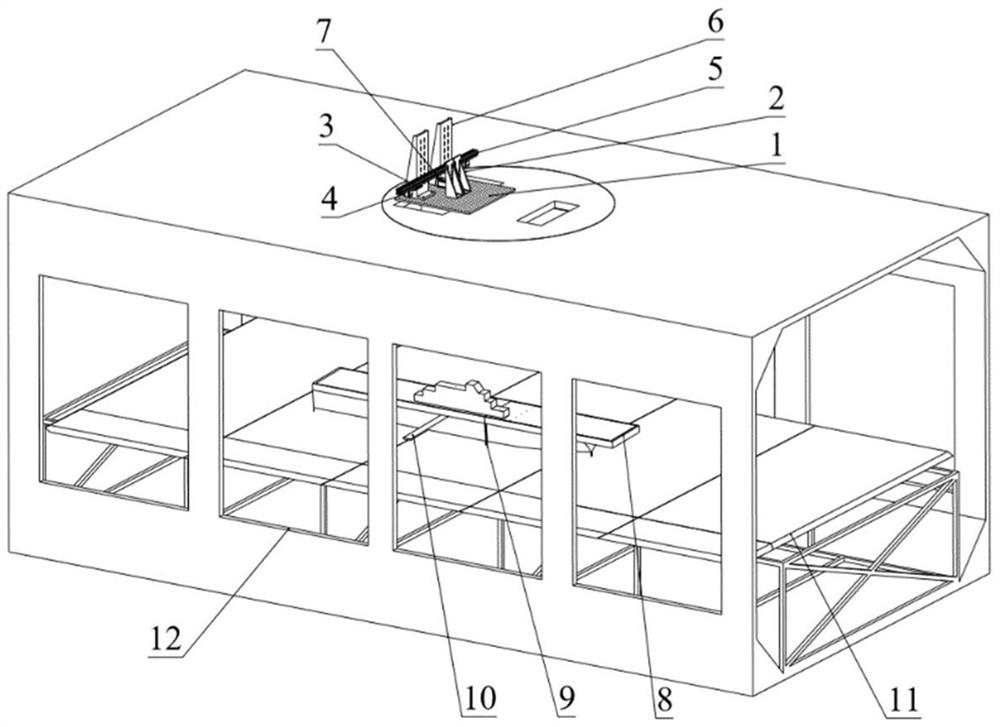
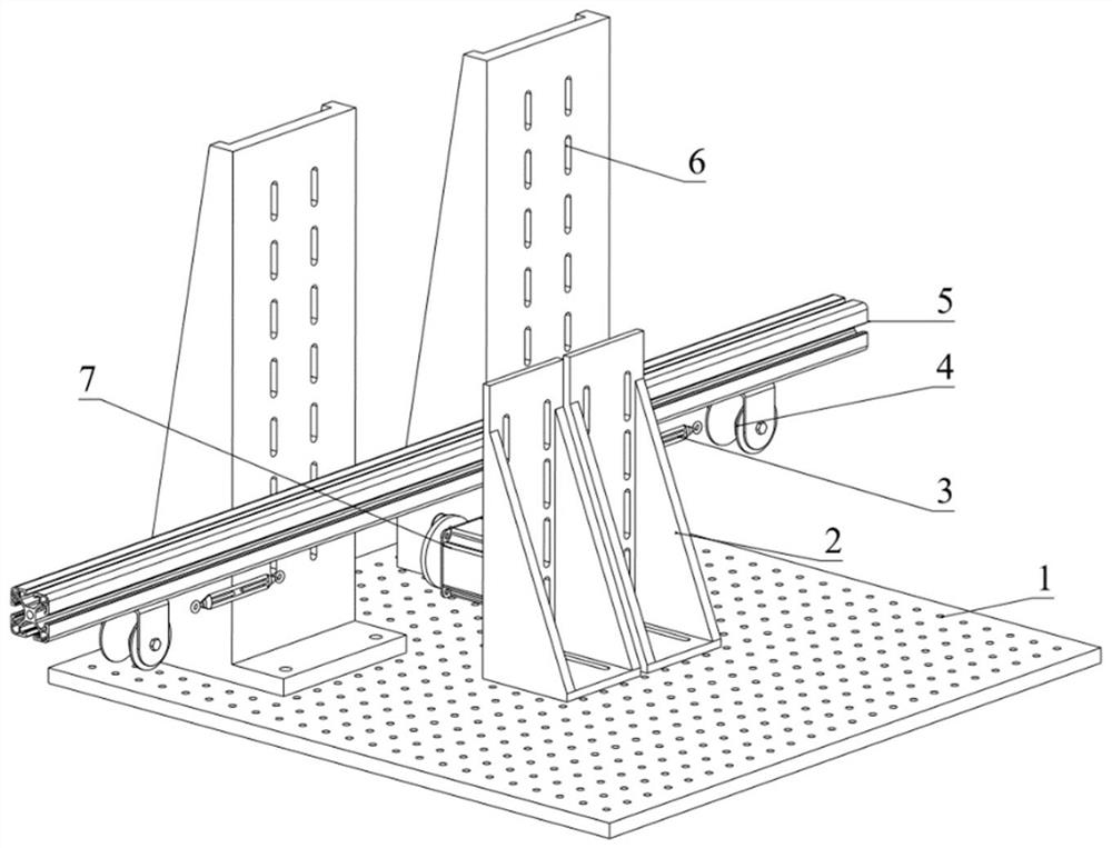
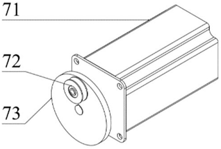
[0050] Such as Figure 7 and 8 As shown, the ship attitude dynamic simulation system used in the wind tunnel test in this embodiment simulates the rolling motion. One lug 10, two lugs 10 are symmetrical with respect to the central axis of the ship model 8, pulleys 4 are installed at both ends of the support rod 5; Pass the pulley 4 on the support bar 5 and be fixed on the slot hole of the other lug 10, and the middle part of the stay cord is fixed on the U groove bearing 72. During the installation process, ensure that the lug 10 slots, the pulley 4 and the turnbuckle 3 are located on the axial symmetry plane of the U-groove bearing 71 .

[0051] According to the maximum angle θ of the rolling motion to be simulated, use the following formula to calculate the distance r between the U-groove bearing 72 and the center hole of the motor turntable 73 1 :

[0052] r 1 =(1 / 2 b+l)×sinθ (1)

[0053] In the formula, b is the width of the bottom of the ship model 8, and l is the d...

Embodiment 2

[0058] Such as Figure 9 As shown, the ship attitude dynamic simulation system used in the wind tunnel test in this embodiment simulates the pitch motion, the center axis of the bottom of the ship model 8 is perpendicular to the center axis of the ship model 8, and an ear piece is installed at the tail of the ship model 8 10. A pulley 4 is installed at one end of the support rod 5 near the afterbody of the ship model 8; A pulley 4 may also be installed on the inner surface of the upper wall plate of the wind tunnel to change the direction of the stay rope.

[0059] According to the maximum angle φ of the pitch motion to be simulated, the distance r between the U-groove bearing 72 and the center hole of the motor turntable 73 is calculated by the following formula 2 :

[0060] r 2 =(1 / 2 c+l)×sinφ

[0061] In the formula, c is the total length of the bottom of the ship model 8, and l is the distance from the bottom edge of the ship model 8 to the slot hole on the lug 10. Af...


PUM


Abstract

The invention discloses a ship attitude dynamic simulation system and a working method thereof for wind tunnel tests. Boat model bases, lugs and aviation floors. The simulation system of the present invention is small in size, and only needs to be installed above the wind tunnel, and the model is stretched and connected by a pull rope, which does not affect the blockage of the wind tunnel flow field; the system has few components, which is convenient for installation and debugging in the wind tunnel environment, pitching, The maximum angle of the roll can be adjusted by adjusting the height of the model; it can also reduce the influence of the wind load in the test according to the weight of the model, so that the accuracy of the roll and pitch motion angles of the ship motion simulation is within 0.5°; This system can also be used with relevant experimental equipment and instruments, and then can realize a series of dynamic experiments such as dynamic balance force measurement, dynamic pressure measurement, dynamic PIV phase-locked flow field measurement, etc., which greatly enriches the dynamic wind tunnel test of large ship models content.

Description

technical field [0001] The invention belongs to the technical field of wind tunnel tests, in particular to a ship attitude dynamic simulation system for wind tunnel tests and a working method thereof. Background technique [0002] The complex flow field environment on the ship deck has always been one of the prominent factors that endanger the safety of shipboard helicopter takeoff and landing and the safety of operations near ships. The vortex generated by sea surface air blowing over the edge of the hull, the turbulent flow formed behind the superstructure of the hull, and the swinging motion of the hull caused by wind and waves will all affect the aerodynamic load of the helicopter, thus bringing many advantages to the maneuverability and stability of the shipborne helicopter. challenge. [0003] For the ship deck flow field, when the ship sails at sea, its air flow field will not only be disturbed by the free flow, but also be affected by the six degrees of freedom ship...

Claims


Application Information

Patent Timeline
Patent Type & Authority Patents(China)
IPC IPC(8): G01M9/08G01M9/04G01M9/06
CPCG01M9/04G01M9/06G01M9/062G01M9/08
Inventor 陈尹张召明顾蕴松吴思雨孙亘
Owner NANJING UNIV OF AERONAUTICS & ASTRONAUTICS
Why Eureka
Try Eureka