Quadrature-direct axis reluctance controllable permanent magnet brushless motor

A permanent magnet brushless motor, controllable technology, applied to synchronous motors with stationary armature and rotating magnets, magnetic circuit shape/style/structure, magnetic circuit, etc., can solve the problem of power density reduction and torque insufficiency Adjustment, air gap main magnetic flux is not high, etc., to achieve the effect of improving the utilization rate reduction, widening the speed regulation range, and high torque density

Active Publication Date: 2020-02-25
JIANGSU UNIV
View PDF11 Cites 4 Cited by
  • Summary
  • Abstract
  • Description
  • Claims
  • Application Information

AI Technical Summary

Problems solved by technology

Although the reluctance motor has the advantages of low cost and low loss, its torque density and speed range are difficult to meet the needs of electric vehicles
The motor disclosed in the document of Chinese Patent Publication No. CN109450211A forms a permanent magnet-assisted synchronous reluctance motor through a built-in permanent magnet in a tangential slot in a U-shaped slot. Although this type of motor utilizes reluctance torque and permanent magnet rotation The torque can improve the torque density, efficiency, etc., but there are problems such as non-adjustable torque and narrow operating range of the motor.
Chinese patent No. 200810023409.X proposes a flux-memory stator permanent-magnet motor that uses DC magnetized windings and AlNiCo permanent magnets to cooperate with each other to achieve wide speed regulation. Current and small weak magnetic current widen the speed range, but due to the additional winding for online adjustment of the air gap magnetic field strength, the motor space utilization rate is low and the power density is reduced
In addition, the permanent magnet magnetic energy product used in the permanent magnet memory motor is low, and the permanent magnet operating point is easily affected by the magnetic field of the armature winding, resulting in low air gap main flux

Method used


Image

  • Quadrature-direct axis reluctance controllable permanent magnet brushless motor
  • Quadrature-direct axis reluctance controllable permanent magnet brushless motor
  • Quadrature-direct axis reluctance controllable permanent magnet brushless motor

Examples


Embodiment Construction

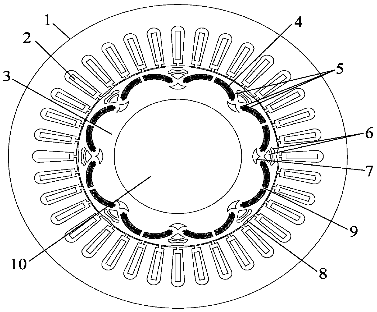
[0031] see figure 1 , the present invention includes a stator core 1 , an armature winding 2 , a rotor core 3 and a rotating shaft 10 . The outermost part is the stator core 1 , the rotor core 3 is located inside the stator core 1 , and the center of the rotor core 3 is slotted for placing the rotating shaft 10 . There is an air gap between the inner wall of the stator core 1 and the outer wall of the rotor core 3, and the thickness of the air gap is related to the power level of the motor, the mixed permanent magnet material, and the processing and assembly processes of the stator core 1 and the rotor core 3. The stator core 1 and the rotor core 3 are formed by laminating silicon steel sheets of the same thickness, the lamination thickness is 0.35 mm, and the lamination coefficient is 0.95. The shaft 10 is made of non-magnetic material.

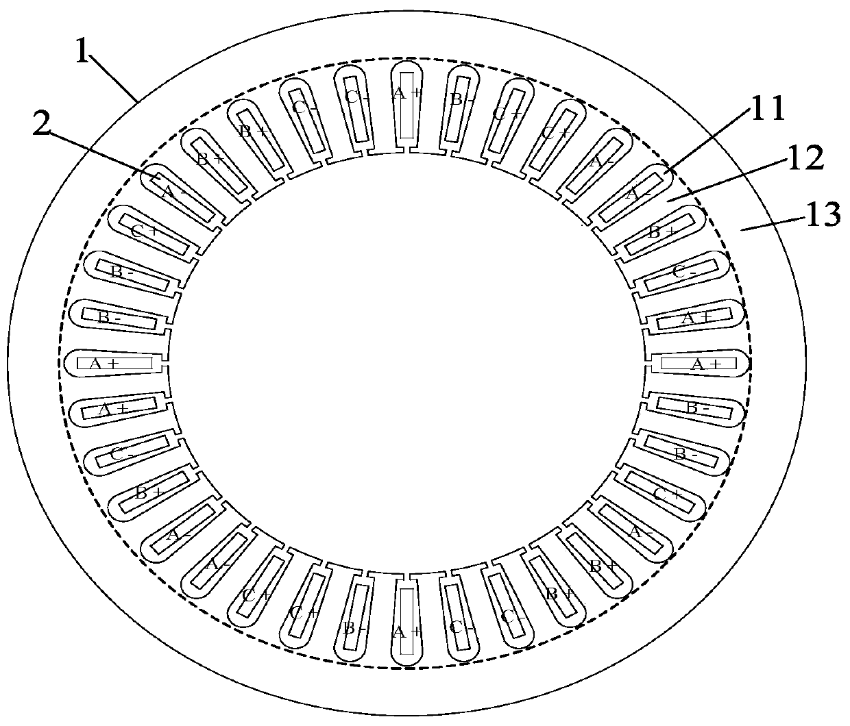
[0032] see figure 2 , The stator core 1 is composed of a stator slot 11 , a stator tooth 12 and a stator yoke 13 . The inner wall of t...


PUM


Abstract

The invention discloses a quadrature-direct axis reluctance controllable permanent magnet brushless motor in the field of motor manufacturing. A stator core is arranged at the outermost part; eight groups of mixed permanent magnets are uniformly embedded in a rotor core along the circumferential direction; each group of mixed permanent magnets consists of two neodymium-iron-boron permanent magnetsand six aluminum-nickel-cobalt permanent magnets; three aluminum-nickel-cobalt permanent magnets are embedded in each neodymium-iron-boron permanent magnet; each group of mixed permanent magnets aresymmetrically arranged relative to the direct axis; a magnetic conductive bridge is formed between the two neodymium-iron-boron permanent magnets in each group of mixed permanent magnets; two adjacentgroups of mixed permanent magnets are symmetrically arranged relative to the quadrature axis; each neodymium-iron-boron permanent magnet and each aluminum-nickel-cobalt permanent magnet are of an arc-shaped structure; three aluminum-nickel-cobalt permanent magnets are embedded in one end, close to the quadrature axis, of each neodymium-iron-boron permanent magnet; one of the three aluminum-nickel-cobalt permanent magnet exists in each layer along the radial direction; and the rotor core between two adjacent groups of mixed permanent magnets is provided with multiple layers of inner and outermagnetic barriers which are symmetrically distributed relative to a quadrature axis, and variable permanent magnet torque is generated through the combined action of the two types of permanent magnets.

Description

technical field [0001] The invention belongs to the field of motor manufacturing, and relates to a permanent magnet brushless motor, which is used to drive a hybrid vehicle and a pure electric vehicle, in particular to a high-torque permanent magnet brushless motor with controllable reluctance of an AC-D axis. Background technique [0002] The development of hybrid electric vehicles and pure electric vehicles is accelerating, and the performance requirements of vehicle drive motors are gradually increasing. The traditional permanent magnet brushless motor is widely used in the drive system of electric vehicles due to its simple structure, high power density, and strong reliability. Since the permanent magnet brushless motor uses a single permanent magnet such as NdFeB as the excitation source, it has a constant air gap magnetic field and a narrow field-weakening speed range. It is very important to increase the torque and widen the speed range of the motor. [0003] Existi...

Claims


Application Information

Patent Timeline
Patent Type & Authority Applications(China)
IPC IPC(8): H02K21/14H02K21/02H02K1/27H02K1/16H02K3/12
CPCH02K1/165H02K1/276H02K3/12H02K21/028H02K21/14H02K2213/03
Inventor 朱孝勇刘玫王腾光周雪吴文叶
Owner JIANGSU UNIV
Why Eureka
Try Eureka