Diagnosis and treatment bed for department of cardiology and utilization method

A technology of diagnosis and treatment bed and cardiology department, applied in the field of medical equipment, can solve the problems of slow blood flow, prone to bed sores, increase of medical care costs, etc., and achieve the effect of low sound

Inactive Publication Date: 2020-02-28
于洋
View PDF0 Cites 1 Cited by
  • Summary
  • Abstract
  • Description
  • Claims
  • Application Information

AI Technical Summary

Problems solved by technology

[0002] Most of the patients treated in the Department of Cardiology are those with limited mobility and difficulty in sitting or lying down. Moreover, most of the patients in the Department of Cardiology are elderly. These elderly people have slow blood flow, and they are bedridden fo...

Method used


Image

  • Diagnosis and treatment bed for department of cardiology and utilization method
  • Diagnosis and treatment bed for department of cardiology and utilization method
  • Diagnosis and treatment bed for department of cardiology and utilization method

Examples


Embodiment 1

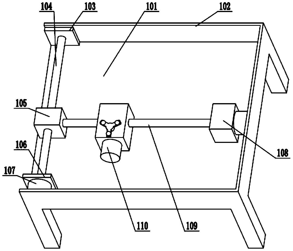
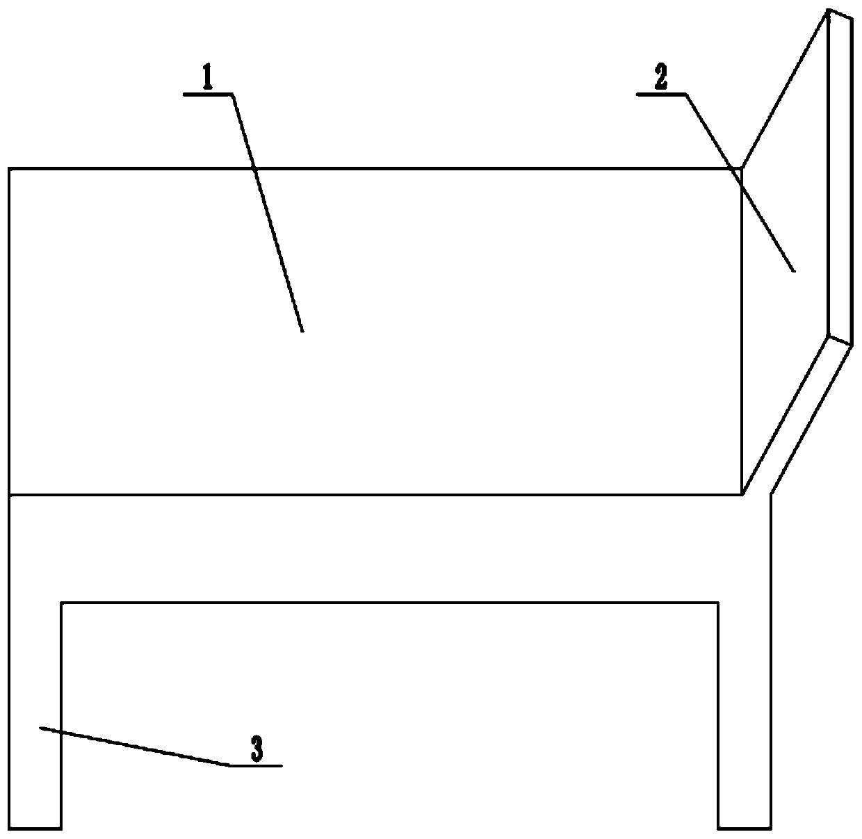
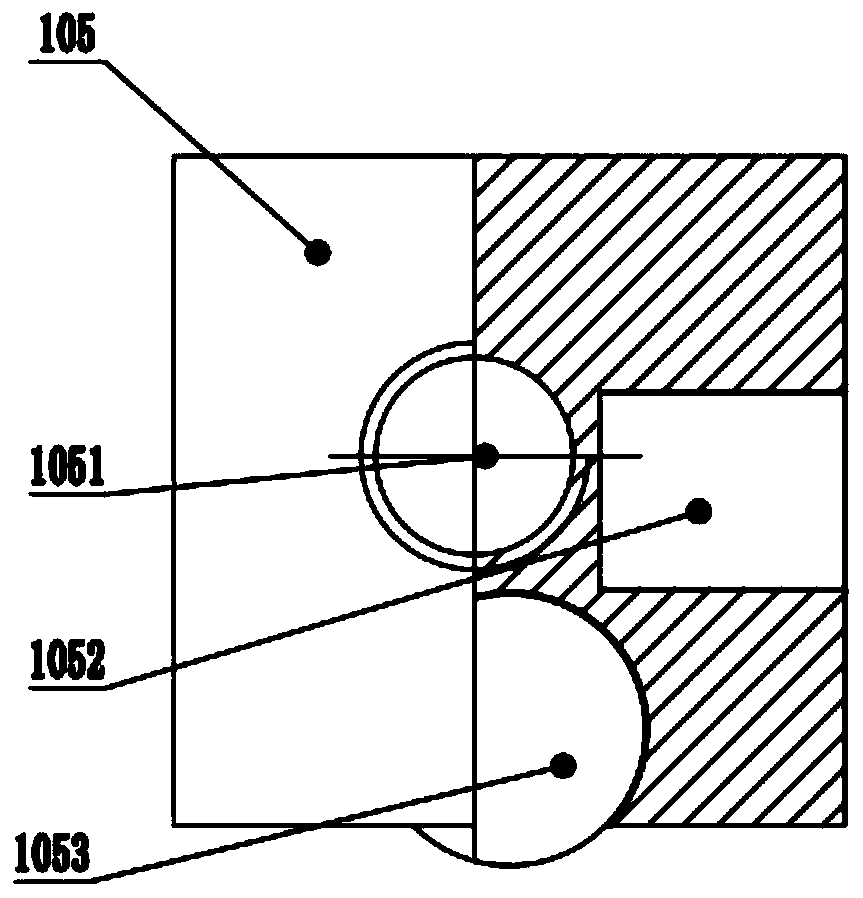
[0027] A cardiology diagnosis and treatment bed in this embodiment includes a bed body 1, a backrest 2, and bed legs 3. The bed body includes a lower board 101 and a vertical board 102. The lower board is arranged on the bed legs, and the vertical board is arranged on the upper part of the lower board. The edge, the flexible pad is arranged on the vertical board, and the backrest is arranged on the vertical board on the side of the head of the bed; it is characterized in that it also includes a flexible pad 100, an X screw plate 103, an X screw 104, a Y screw seat 105, and an X screw seat. Motor plate 106, X motor 107, Y motor seat 108, Y leading screw 109, massage seat 110; Flexible pad 100 is located on vertical plate; The plane is parallel to the vertical plate on the long side of the bed body 1, the X motor 107 is fixed on the X motor plate 106, and the X motor 107 motor shaft is connected to the X lead screw 104 through a shaft coupling; the X lead screw plate 103 is verti...

Embodiment 2

[0034]A method for using a cardiology diagnosis and treatment bed. After the bed is placed, the power is turned on, and the patient is placed. When the patient feels physically tired, he operates and controls the rotation of the X motor 107 on the operation panel to drive the Y motor base 108, the Y screw 109 and Massage seat 110 moves in X direction; then control Y motor 1081 to drive Y lead screw 109, drive massage seat 110 to move longitudinally, massage seat 110 is moved to the place that needs massage, then control massage motor 1101 to run, drive massage claw 1103 to rotate, massage the body For massage, the three motors operate separately, and they are controlled to rotate simultaneously. When the massage seat 110 moves, the massage claws 1103 rotate simultaneously to perform mobile massage; the motor drives the lead screw to drive the massage seat 110 to move under the flexible pad 100. The speed of the motor is selected according to the needs of the patient. The sound ...


PUM


Abstract

The invention discloses a diagnosis and treatment bed for a department of cardiology. The diagnosis and treatment bed comprises a bed body, a backrest and bed legs, the bed body comprises a lower board and vertical boards, the lower board is arranged on the bed legs, the vertical boards are arranged at the upper edges of the lower board, and the backrest is arranged on the vertical board on one side of a head of the bed. The diagnosis and treatment bed is characterized by further comprising a flexible mattress, an X screw plate, an X screw, a Y screw seat, an X motor plate, an X motor, a Y motor seat, a Y screw and a massage seat. The flexible mattress is arranged on the vertical boards; the X motor is fixed to the X motor plate, and a motor shaft of the X motor is connected with the X screw through a coupler. The screws are driven by the motors to drive the massage seat to move under the flexible mattress, the speeds of the motors can be selected according to requirements of a patient, the motors and the screws are low in operating noise, and further, by the soundproof effect of the flexible mattress and quilts, the patient can have massage without affecting rest. In addition, byadoption of the X and Y screws, motion positions of the massage seat can cover the whole flexible mattress, so that massage of the whole body including waist, back, buttocks, legs and the like of thepatient is guaranteed.

Description

technical field [0001] The invention relates to the field of medical appliances, in particular to a cardiology diagnosis and treatment bed. Background technique [0002] Most of the patients treated in the Department of Cardiology are those with limited mobility and difficulty in sitting or lying down. Moreover, most of the patients in the Department of Cardiology are elderly. These elderly people have slow blood flow, and they are bedridden for a long time and cannot walk around, which leads to decubitus ulcers on the back, buttocks and other parts. , need nurses to turn over and massage them frequently, increase the cost of medical care, now need a kind of treatment bed that can automatically massage patients. Contents of the invention [0003] The object of the present invention is to provide a cardiology diagnosis and treatment bed to solve the problems raised in the above-mentioned background technology. [0004] To achieve the above object, the present invention pro...

Claims


Application Information

Patent Timeline
IPC IPC(8): A61H7/00A61G13/10
CPCA61G13/0018A61G13/009A61G13/10A61G2203/10A61H7/00A61H2201/0142A61H2201/1207
Inventor 于洋
Owner 于洋
Why Eureka
Try Eureka