
Fabricated wall temporary connecting and fixing equipment

A technology for temporary connection and fixing of equipment, which is applied in the direction of construction, building structure, and building material processing. It can solve the problems of good compression and reinforcement effects, high work efficiency, and increased safety accidents. Good connection and fixation, high work efficiency

Active Publication Date: 2020-02-28
江苏邦得绿建装饰有限公司
View PDF8 Cites 12 Cited by
  • Summary
  • Abstract
  • Description
  • Claims
  • Application Information

AI Technical Summary

Problems solved by technology

[0003] However, the following problems exist in the assembly of the current prefabricated walls. 1. After most of the prefabricated walls are assembled in place, the prefabricated walls cannot be placed stably when the joint construction is not completed, and manual support is usually used. The rod temporarily abuts the prefabricated wall, which greatly increases the possibility of safety accidents, and cannot firmly abut the prefabricated wall; 2. The traditional reinforcement device needs to set threaded holes on the wall, using threaded The rod installs the steel plate in the threaded hole of the wall, welds the upper end of the support rod to the steel plate, and buries the lower end of the support rod on the ground, which is not only time-consuming and laborious, but also has structural damage to the assembled wall, and has the effect of pressing and strengthening Good and high work efficiency

Method used


Image

  • Fabricated wall temporary connecting and fixing equipment
  • Fabricated wall temporary connecting and fixing equipment
  • Fabricated wall temporary connecting and fixing equipment

Examples


Embodiment Construction

[0027] The embodiments of the present invention will be described in detail below with reference to the accompanying drawings, but the present invention can be implemented in many different ways defined and covered by the claims.

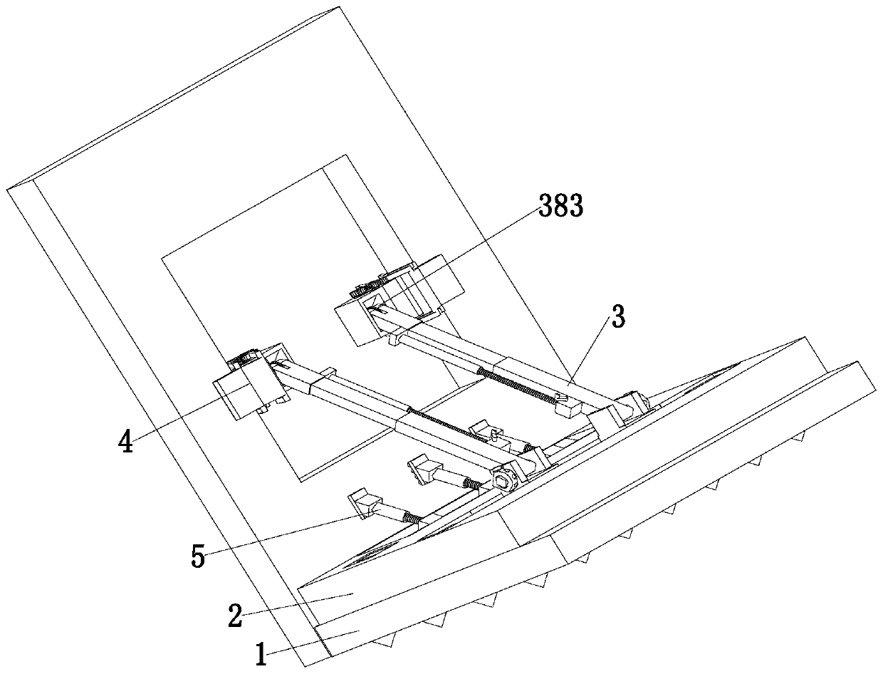
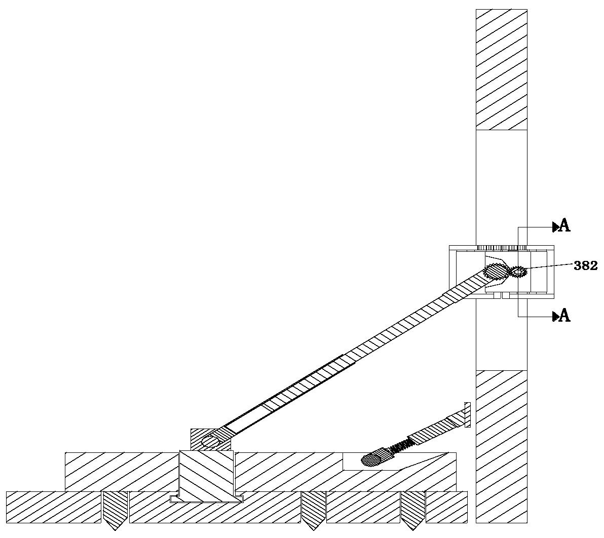
[0028] Such as Figure 1 to Figure 8 As shown, a prefabricated wall temporary connection and fixing device includes a base plate 1, a flat plate 2, a support device 3, a clamping device 4 and a pressing device 5. A flat plate 2 is installed on the base plate 1, and the left and right sides of the base plate 1 Supporting devices 3 are installed symmetrically at both ends, a clamping device 4 is installed on the supporting device 3 , and a pressing device 5 is installed on the flat plate 2 .

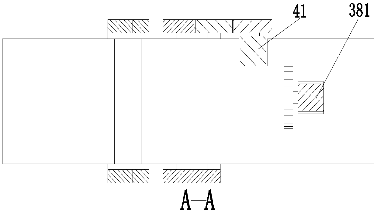
[0029] The support device 3 includes a telescopic support rod 31, a straight plate 32, a support slider 33, a retractable cylinder 34, an insertion shaft 35, a hollow ring 36 and an insertion rod 37. Slot, shrinking cylinder 34 is installed symmetrically on the...


PUM


Abstract

The invention relates to fabricated wall temporary connecting and fixing equipment. The fabricated wall temporary connecting and fixing equipment comprises a base plate, a flat plate, supporting devices, clamping devices and pushing devices. The flat plate is mounted on the base plate. The supporting devices are symmetrically mounted at the left and right ends of the base plate. The clamping devices are mounted on the corresponding supporting devices. The pushing devices are mounted on the flat plate. Through the fabricated wall temporary connecting and fixing equipment, the following problemsexisting during fabrication of an existing fabricated wall can be solved. The problems are shown as follows: when most of fabricated walls are assembled in place and joint construction is not completed, the fabricated walls can be placed stably and the occurrence possibility of accidents is greatly improved; and when traditional reinforcing devices are adopted, threaded holes need to be formed inthe walls, steel plates are mounted to the threaded holes of the walls through threaded rods, the upper ends of supporting rods are welded to the steel plates, the lower ends of the supporting rods are embedded on the ground, a lot of time and labor are wasted, and structural damage is caused to the fabricated walls. The fabricated wall temporary connecting and fixing equipment has the advantagesof being good in pushing and reinforcing effect, high in working efficiency and the like.

Description

technical field [0001] The invention relates to the technical field of prefabricated buildings, in particular to a temporary connection and fixing device for prefabricated walls. Background technique [0002] The prefabricated building that has emerged in recent years is a typical representative of green buildings. It not only represents a new round of technological revolution and industrial transformation in the construction industry, but also a major change in construction methods. It is not only conducive to saving resources and energy, but also improving labor production efficiency and quality. The level of safety is more conducive to promoting the deep integration of the construction industry and information industrialization, improving the industrialization level of buildings and resource utilization, and promoting the industrialization and industrialization of buildings. At present, construction projects have gradually transformed from cast-in-place concrete structures...

Claims


Application Information

Patent Timeline
Patent Type & Authority Applications(China)
IPC IPC(8): E04G21/26
CPCE04G21/26
Inventor 张亚张晋源
Owner 江苏邦得绿建装饰有限公司
Learn More