

Pose calibration method and system for laser radar and combined inertial navigation, and medium
A laser radar and pose calibration technology, applied in the computer field, can solve the problems of high cost, large error, and affecting the accuracy of pose calibration, and achieve the effect of improving accuracy and reducing calibration cost
- Summary
- Abstract
- Description
- Claims
- Application Information
AI Technical Summary
Problems solved by technology
Method used
Image



Examples
Embodiment 1
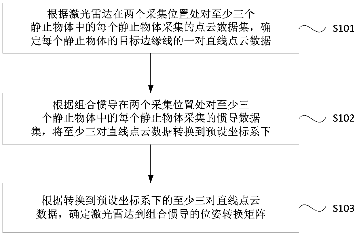
[0031] figure 1 It is a flow chart of a pose calibration method for lidar and integrated inertial navigation provided by Embodiment 1 of the present invention. This embodiment is applicable to how to accurately calibrate the relative pose between lidar and integrated inertial navigation. The method can be executed by the control device in the surveying and mapping system of the embodiment of the present invention, and the control device can be realized by software and / or hardware. like figure 1 As shown, the method specifically includes the following steps:
[0032] S101. Determine a pair of straight line point cloud data of a target edge line of each stationary object based on the point cloud data sets collected by the lidar at two collection positions for each of the at least three stationary objects.
[0033] Wherein, the laser radar is a radar system that emits laser beams to detect the position of an object. Optionally, the laser radar in this embodiment may be a multi-...
Embodiment 2
[0052] Figure 2A It is a flowchart of a pose calibration method of a laser radar and an integrated inertial navigation system in Embodiment 2 of the present invention, Figure 2B It is a schematic diagram of the installation orientation of the laser radar according to the embodiment of the present invention. This embodiment is further optimized on the basis of the above embodiments, and specifically gives an introduction of how to obtain the point cloud data set and the inertial navigation data set of each stationary object. like Figure 2A As shown, the method of this embodiment specifically includes the following steps:
[0053] S201. Acquire point cloud data sets and inertial navigation data sets collected from each of the at least three stationary objects at two collection positions by the rigidly connected lidar and integrated inertial navigation.
Embodiment approach
[0055] Possible implementation mode 1. For each of the at least three stationary objects, sequentially acquire the point cloud data set and the inertial navigation data set collected by the rigidly connected lidar and the combined inertial navigation at two collection positions for the stationary object .
[0056] Specifically, in this embodiment, the rigidly connected lidar and combined inertial navigation can only collect point cloud data sets and inertial navigation data sets of a stationary object at one collection position at a time. That is to say, the rigidly connected lidar and combined inertial navigation are performed once for each stationary object in at least three stationary objects, and the point cloud data set and the inertial navigation data set are collected twice at two different collection positions. The data finally collected in this embodiment is to include two sets of point cloud data sets (i.e. the first point cloud data set and the second point cloud da...
PUM
 Abstract
Description
Claims
Application Information