High-voltage non-inductive resistor and DC voltage measuring device

A non-inductive resistance, high-voltage technology, applied in the direction of measuring devices, measuring current/voltage, resistors, etc., can solve the problems of high electric field strength, corona discharge, leakage current, etc., to increase the corona inception voltage and reduce the electric field strength , Improve the effect of measurement accuracy

Inactive Publication Date: 2020-02-28
西安西电高压开关有限责任公司 +1
View PDF6 Cites 0 Cited by
  • Summary
  • Abstract
  • Description
  • Claims
  • Application Information

AI Technical Summary

Problems solved by technology

[0003] Among them, the non-inductive resistor with forward and reverse helical structure is composed of forward and reverse helical resistor strings connected in series, the electromagnetic field formed is only partially offset, but the inductance of the resistor still exists, and if one of the resistor strings is damaged, the entire resistance will be damaged. Failure, this non-inductive resistor is prone to corona under high voltage
[0004] The manufacturing process of wire-wound non-inductive resistors requires high requirements, and the electric field structure of the resistor is complex, and the electric field strength is large. Under high voltage, it is also easy to generate corona.
[0005] In some electrical appliances that are sensitive to inductance and electric field, such as DC voltage measuring devices, when the electric field strength on the surface of the high-voltage resistance of the high-voltage arm is too large, there will be corona discharge and leakage current, which will affect the measurement accuracy.
The high-voltage resistors used in the high-voltage arm must be non-inductive resistors. If the inductance of the high-voltage resistors is too large, it will affect the response characteristics of the product, and it will cause damage to the high-voltage resistors or other electronic devices when subjected to high-voltage shocks.

Method used


Image

  • High-voltage non-inductive resistor and DC voltage measuring device
  • High-voltage non-inductive resistor and DC voltage measuring device

Examples


Embodiment Construction

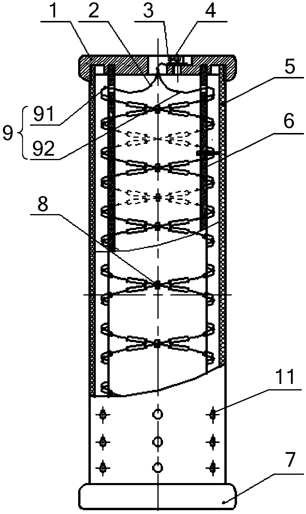
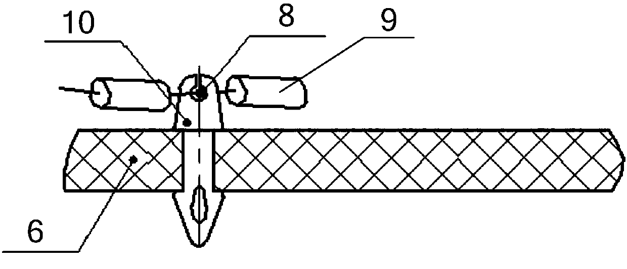
[0034] The core of the present invention is to provide a high-voltage non-inductive resistor, which reduces its inductance and electric field strength during operation.

[0035] The invention also provides a DC voltage measuring device containing the high-voltage non-inductive resistance, which improves the measurement accuracy and protects it from damage.

[0036] The technical solutions in the embodiments of the present invention will be clearly and completely described below in conjunction with the accompanying drawings in the embodiments of the present invention. Obviously, the described embodiments are only a part of the embodiments of the present invention, rather than all the embodiments. Based on the embodiments of the present invention, all other embodiments obtained by those of ordinary skill in the art without creative work shall fall within the protection scope of the present invention.

[0037] Please refer to figure 1 The embodiment of the present invention provides a h...


PUM


Abstract

The invention discloses a high-voltage non-inductive resistor and a DC voltage measuring device. The high-voltage non-inductive resistor comprises an internal insulation tube; an outer insulation tube, wherein the inner insulation tube is sleeved in the outer insulation tube, and the two ends of the outer insulation tube and the inner insulation tube are closed; and at least one pair of resistancestring group which is located between that inner insulation tube and the outer insulation tube, and each pair of resistance string group comprises two resistance strings with opposite spiral directions and symmetrically arranged relative to a plane passing through the axis of the inner insulation tube, and the resistance string group forms a pipe network circuit structure. The spiral directions of the two resistance strings of each pair of resistance string group are opposite and symmetrically arranged, the resistor becomes the tubular network circuit structure, theoretically the inductance value is zero and the electric field strength on the surface of the resistor is greatly reduced during operation the high-voltage non-inductance resistor.

Description

Technical field [0001] The invention relates to the technical field of electrical components, in particular to a high-voltage non-inductive resistor. The invention also relates to a DC voltage measuring device containing the high-voltage non-inductive resistance. Background technique [0002] Non-inductive resistance refers to a resistance with zero inductance. The existing non-inductive resistors mainly include non-inductive resistance with positive and negative spiral structure and wire-wound non-inductive resistance. [0003] Among them, the non-inductive resistance of the positive and negative spiral structure is formed by the positive spiral resistor string and the reverse spiral resistor string. The electromagnetic field formed is only partially offset, but the inductance of the resistor still exists, and if one of the resistor strings is damaged, the entire resistor will be caused Failure, this non-inductive resistor is prone to corona under high voltage. [0004] The manufa...

Claims


Application Information

Patent Timeline
Patent Type & Authority Applications(China)
IPC IPC(8): H01C1/024G01R19/00
CPCG01R19/00H01C1/024
Inventor 雷鹏曾林翠马洪义张春基李亮亮侯彦杰王璐
Owner 西安西电高压开关有限责任公司
Why Eureka
Try Eureka