Rotating anode electrostatic precipitator

A technology of electrostatic precipitator and rotary anode, applied in the field of electrostatic precipitator and rotary anode electrostatic precipitator, can solve the problems of unguaranteed sealing, single selection, poor dust removal effect, etc., to reduce costs and equipment load , The current density distribution is uniform, the effect of reducing the material and weight

Active Publication Date: 2012-06-06
浙江菲达环保科技股份有限公司
View PDF2 Cites 0 Cited by
  • Summary
  • Abstract
  • Description
  • Claims
  • Application Information

AI Technical Summary

Problems solved by technology

[0005] 1. The distance between different poles between the rotating anode plate and the cathode line is single, and there are problems in the adaptability to dust and the selection of power supply
[0006] 2. Both ends of the driven roller of the rotary anode device are fixed with bearings, the center distance between the driven roller and the driving roller cannot be adjusted, and the wear between the main and driven sprockets and the transmission chain will inevitably cause the transmission chain to loosen, affecting Smooth operation of the rotary anode unit, thereby affecting efficient and stable operation of the electric field
[0007] 3. The center distance of the rotating brush assembly cannot be continuously adjusted, so that the rotating brush assembly cannot always provide a suitable cleaning force for the anode plate, and the sealing performance cannot be guaranteed when the center distance of the rotating brush assembly is adjusted, which will cause air leakage of the equipment and affect the ash The insulation performance of the hopper and the fluidity of the dust removal ash are likely to cause ash hopper clogging failure
[0008] 4. Generally, the prickly type cathode wire is used, the current density distribution is not uniform enough, and the dust removal effect is poor for the dust characteristics of the final electric field of low concentration and fine dust.

Method used


Image

  • Rotating anode electrostatic precipitator
  • Rotating anode electrostatic precipitator
  • Rotating anode electrostatic precipitator

Examples


Embodiment Construction

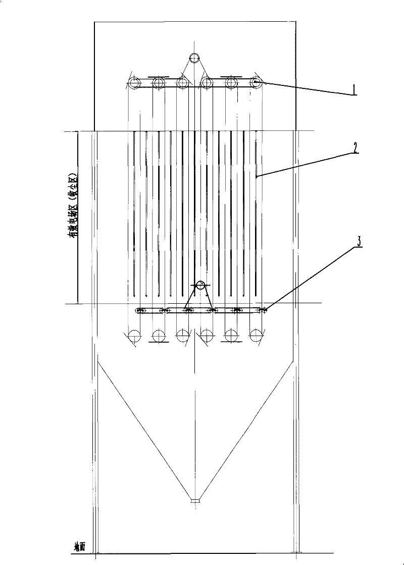
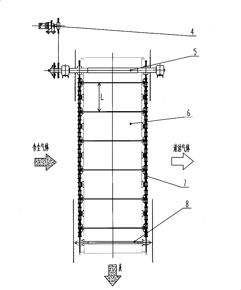
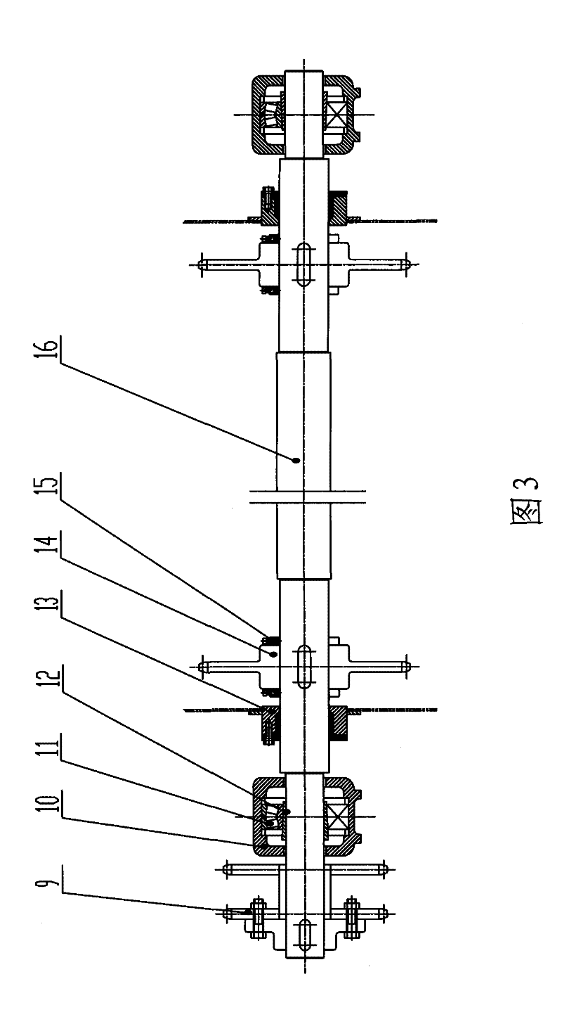
[0032] Such as figure 1 , 2 As shown, the present invention mainly includes a rotary anode device 1, a cathode wire 2 and a rotary steel brush cleaning mechanism 3. The rotary anode device 1 includes a driving roller 5, an anode plate 6, a transmission chain 7 and a driven roller 8, wherein the driving roller 5, the transmission chain 7 and the driven roller 8 form a chain transmission mechanism, and the anode plate 6 is fixed by bolts. On a pair of symmetrical drive chains 7. The reducer 4 provides power to the rotary anode device 1 through a chain drive, so that the anode plate 6 can rotate in a ring along with the transmission chain 7 . The speed of reducer 4 is adjustable; the cathode wire 2 adopts a spiral wire, which is installed in the middle of the anode plate 6, and a high-voltage electric field is applied between the cathode wire 2 and the anode plate 6. When the dust-containing gas enters the electric field, the gas is ionized and the dust is charged. 1. The char...


PUM


Abstract

The invention discloses a rotating anode electrostatic precipitator, comprising a rotating anode device, a cathode ray and a rotary steel brush ash-cleaning mechanism, the rotating anode device comprises a drive roller, a driven roller, a drive sprocket which connects the drive roller and the driven roller, a drive chain and an anode plate which is connected on the drive chain, the heteropolar distance between the anode plate and the cathode ray is 200mm or 230mm or 260mm; the driven roller adopts a free suspension structure and can ensure the automatic centering of the driven roller and the free tightening of the drive chain; the rotary steel brush ash-cleaning mechanism comprises at least one pair of ash-cleaning brush components which rotate reversely, the central distance of each pairof the ash-cleaning brush components which rotate reversely is continuously adjustable, and movable sealing devices are arranged at two ends of each ash-cleaning brush component. The rotating anode electrostatic precipitator simultaneously takes into account of secondary blowing dust, dust-removing effect, occupied area and equipment cost. An electric field can operate efficiently and stably, thecost and the equipment load are reduced, and the service life is simultaneously prolonged.

Description

【Technical field】 [0001] The invention relates to an electrostatic precipitator, in particular to a rotating anode electrostatic precipitator with a cleaning brush, which belongs to the field of flue gas dust removal in air pollution control. It can be applied to the efficiency improvement of new equipment or old equipment of dust removal device. 【technical background】 [0002] With the increasing awareness of environmental protection and the increasing requirements for environmental protection, the traditional electrostatic precipitator technology can no longer fully meet the requirements, especially in a special coal-fired country like ours, where the types of coal used by boilers are complex and changeable, and some difficulties are still encountered. Coal fly ash (such as high Al 2 o 3 High SiO 2 Low Na 2 O) The effect of electric precipitator is low; the changes in the nature of many dusts after desulfurization have also brought new issues to electric precipitator; ...

Claims


Application Information

Patent Timeline
Patent Type & Authority Patents(China)
IPC IPC(8): B03C3/04B03C3/86B03C3/74B03C3/47B03C3/41F16G13/06F16H55/30F16J15/16
Inventor 郦建国陈招妹王贤明徐小峰郭峰潘民兴余顺利
Owner 浙江菲达环保科技股份有限公司
Why Eureka
Try Eureka