
Fractional-pole two-phase vernier permanent magnet linear motor

A permanent magnet linear motor and vernier technology, applied in magnetic circuits, electromechanical devices, electrical components, etc., can solve the problem of increasing the deformation risk of motor guide rails and system support components, reducing system control accuracy and response speed, electromagnetic thrust and longitudinal magnetic force. Pull force fluctuation and other problems, to achieve the effect of improving control accuracy and operating efficiency, shortening response time, and reducing electromagnetic thrust fluctuation

Active Publication Date: 2020-02-28
HUAZHONG UNIV OF SCI & TECH
View PDF6 Cites 4 Cited by
  • Summary
  • Abstract
  • Description
  • Claims
  • Application Information

AI Technical Summary

Problems solved by technology

[0004] When the linear permanent magnet vernier motor is running, there will be a longitudinal magnetic pull between the permanent magnet pole and the primary of the linear motor; at the same time, due to the inherent edge effect of the traditional permanent magnet linear motor, the electromagnetic thrust and Longitudinal magnetic pull has large fluctuations
The fluctuating longitudinal magnetic pull will not only increase the deformation risk of the motor guide rail and system support components, but also introduce a variable resistance to the system, increase the difficulty of motor control, and reduce the control accuracy and response speed of the system

Method used


Image

  • Fractional-pole two-phase vernier permanent magnet linear motor
  • Fractional-pole two-phase vernier permanent magnet linear motor
  • Fractional-pole two-phase vernier permanent magnet linear motor

Examples


Embodiment Construction

[0026] In order to make the object, technical solution and advantages of the present invention clearer, the present invention will be further described in detail below in conjunction with the accompanying drawings and embodiments. It should be understood that the specific embodiments described here are only used to explain the present invention, not to limit the present invention.

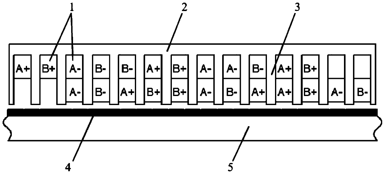
[0027] The present invention introduces the concept of fractional poles, and proposes a fractional pole two-phase vernier permanent magnet linear motor, including: armature winding, primary core yoke, primary core teeth, permanent magnet poles and secondary core;

[0028] The armature winding is wound in the core slot between the teeth of the primary core; the permanent magnet poles are evenly distributed on the secondary core to form a permanent magnet array, and the polarities of adjacent permanent magnet poles are opposite;

[0029] The armature winding, the primary core teeth and the primary co...


PUM


Abstract

The invention discloses a fractional-pole two-phase vernier permanent magnet linear motor, which comprises an armature winding, a primary iron core yoke part, a primary iron core tooth part, permanentmagnet poles and a secondary iron core. The permanent magnet poles are uniformly distributed on the secondary iron core in an array manner, and the polarities of adjacent permanent magnet poles are opposite; the armature winding, the primary iron core yoke part and the primary iron core tooth part form a motor primary; the permanent magnet poles and the secondary iron core form a motor secondary;an air gap exists between the linear motor primary and the linear motor secondary, and the motor primary and the linear motor secondary can move relative to each other. According to the invention, the constraint that the number of effective permanent magnet poles in a traditional vernier permanent magnet linear motor is an even number is canceled, and a fractional pole concept is provided, so that the number of effective permanent magnet poles of the permanent magnet linear motor can be fractional, possible pole slot matching schemes are expanded, and the design freedom degree of the linear motor is improved. According to the invention, while the high thrust density characteristic of the vernier permanent magnet linear motor is maintained, the horizontal thrust fluctuation and the longitudinal magnetic tension fluctuation are reduced, thereby helping to improve the control precision and the response speed of the motor.

Description

technical field [0001] The invention belongs to the technical field of permanent magnet motors, and more specifically relates to a fractional pole two-phase vernier permanent magnet linear motor. Background technique [0002] Compared with the solution of rotating motor and ball screw to form linear motion, the solution of using linear motor to directly generate linear motion has a simpler structure, higher efficiency and better stability. Therefore, linear motors are becoming more and more popular in industrial fields that require linear motion. Linear motors are divided into two categories: linear induction motors and linear permanent magnet motors. Compared with linear induction motors, linear permanent magnet motors have better thrust density, power factor and efficiency performance. Among the many linear motor topologies, the vernier permanent magnet linear motor using the principle of permanent magnet and vernier motor has the characteristics of simple structure and ...

Claims


Application Information

Patent Timeline
Patent Type & Authority Applications(China)
IPC IPC(8): H02K41/03H02K1/16H02K3/12H02K1/27
CPCH02K1/165H02K1/27H02K3/12H02K41/031H02K2213/03
Inventor 李大伟李睿曲荣海石超杰周游
Owner HUAZHONG UNIV OF SCI & TECH
Learn More