Supercharge Your Innovation With Domain-Expert AI Agents!

Continuous feeding, conveying and mounting equipment for mounting of components on circuit layer

A circuit layer and component technology, applied in the direction of electrical components, electrical components, etc., can solve the problems of high welding precision, low efficiency, and inability to give full play to the working efficiency of equipment, and achieve the effect of improving work efficiency and saving labor costs

Active Publication Date: 2020-02-28
蒋超
View PDF3 Cites 4 Cited by
  • Summary
  • Abstract
  • Description
  • Claims
  • Application Information

AI Technical Summary

Problems solved by technology

[0002] Electronic component surface mount equipment is to paste electronic components on the solder paste on the circuit layer, and then weld the electronic components on the circuit layer by hot melting. The device is picked up and placed precisely on a specific position on the circuit layer. Due to the high welding precision requirements of electronic components, traditional equipment cannot work continuously, and the circuit layer can only be processed in sections. The efficiency is low and cannot be fully utilized. The working efficiency of the equipment, and the existing distance between electrical components cannot be adjusted

Method used


Image

  • Continuous feeding, conveying and mounting equipment for mounting of components on circuit layer
  • Continuous feeding, conveying and mounting equipment for mounting of components on circuit layer
  • Continuous feeding, conveying and mounting equipment for mounting of components on circuit layer

Examples


Embodiment Construction

[0031] A specific embodiment of the present invention will be described in detail below in conjunction with the accompanying drawings, but it should be understood that the protection scope of the present invention is not limited by the specific embodiment.

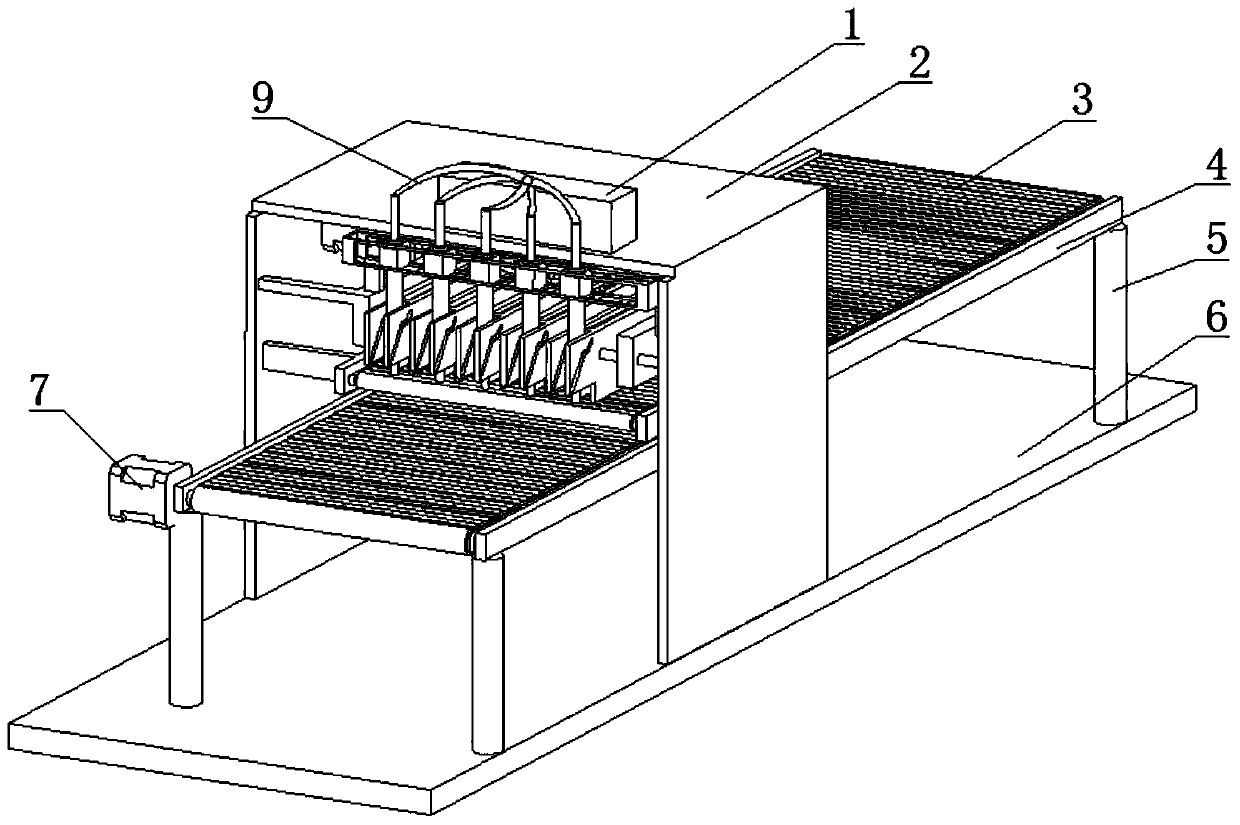
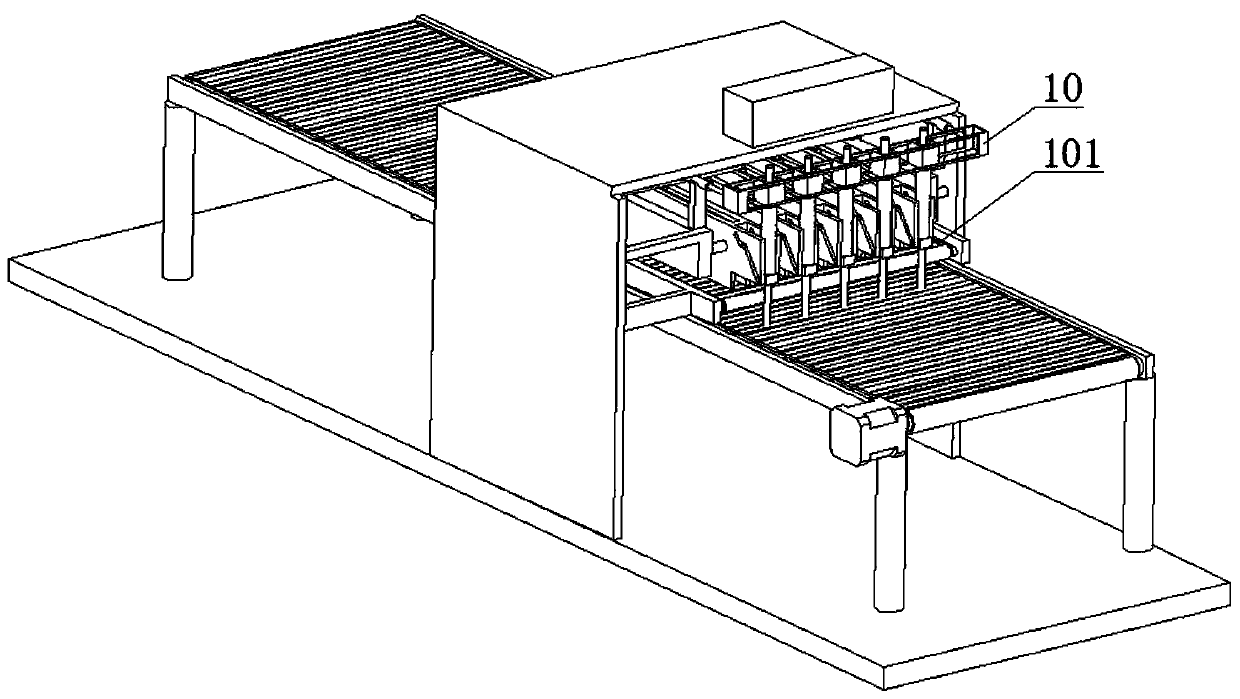
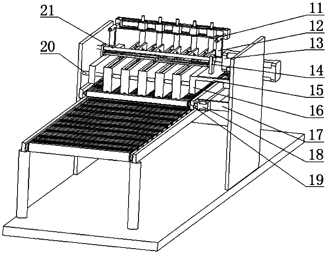
[0032] Such as Figure 1-Figure 11 As shown, the present invention includes a bottom plate 6, the upper side of the bottom plate 6 is fixedly connected to one end of a set of support rods 5, and the other end of each of the support rods 5 is fixedly connected to one end of the corresponding square plate 4, each of which One side of the square plate 4 is respectively hinged to one end of a group of evenly arranged rollers 23, the two ends of each of the rollers 23 are fixedly connected to the runners 42, and the two ends of the conveyor belt 3 surround the corresponding rollers respectively. Roller two 23, the two ends of symmetrical belt one 24 surround corresponding said runner two 42 respectively, one end of one describe...


PUM


Abstract

The invention discloses continuous feeding, conveying and mounting equipment for mounting of components on a circuit layer. The equipment comprises a bottom plate, and is characterized in that the upper side of the bottom plate is fixedly connected with one ends of a set of supporting rods; the other end of each supporting rod is fixedly connected with one end of a corresponding square plate; oneside of each square plate is hinged to one end of a group of uniformly arranged rollers 2; the two ends of each rollers 2 are fixedly and respectively connected with a rotating wheel 2; the two ends of a conveying belt are surrounded by the corresponding rollers 2 respectively; the two ends of a symmetrical belt 1 are surrounded by the corresponding rotating wheels 2 correspondingly; one end of one square plate is fixedly connected with a motor 1; an output shaft of the motor 1 is hinged to one square plate; and a transverse plate of the U-shaped plate is fixedly connected with a mounting mechanism. The invention relates to the field of component conveying and mounting equipment, in particular to the continuous feeding, conveying and mounting equipment for mounting of the components on the circuit layer. The equipment can mount the components on the circuit layer conveniently.

Description

technical field [0001] The invention relates to the field of component conveying and mounting equipment, in particular to a component mounting circuit layer continuous feeding conveying and mounting equipment. Background technique [0002] Electronic component surface mount equipment is to paste electronic components on the solder paste on the circuit layer, and then weld the electronic components on the circuit layer by hot melting. The device is picked up and placed precisely on a specific position on the circuit layer. Due to the high welding precision requirements of electronic components, traditional equipment cannot work continuously, and the circuit layer can only be processed in sections. The efficiency is low and cannot be fully utilized. The working efficiency of the equipment, and the existing ones cannot adjust the distance between the electrical components when they are transported. This is, the weak point of prior art. Contents of the invention [0003] The...

Claims


Application Information

Patent Timeline
Patent Type & Authority Applications(China)
IPC IPC(8): H05K13/00H05K13/04
CPCH05K13/0061H05K13/0417H05K13/046H05K13/0419
Inventor 蒋超
Owner 蒋超
Features
  • R&D
  • Intellectual Property
  • Life Sciences
  • Materials
  • Tech Scout
  • Unparalleled Data Quality
  • Higher Quality Content
  • 60% Fewer Hallucinations
Learn More