
Test trays and sorters for electronic component testing

A technology for electronic components and test trays, which is applied in the field of sorting machines for electronic component testing, can solve problems such as cost burden or reduced processing speed, expensive testing machines, and inability to apply existing technologies, and achieves miniaturization of processing capacity and miniaturization The effect of reducing, reducing resource waste or cost burden

Active Publication Date: 2022-02-08
TECHWING CO LTD
View PDF10 Cites 0 Cited by
  • Summary
  • Abstract
  • Description
  • Claims
  • Application Information

AI Technical Summary

Problems solved by technology

[0013] Therefore, if during the circular movement of the test tray, the moving direction of the test tray carried out in the test section is inconsistent with the step-by-step moving direction (direction perpendicular to the moving direction of the test tray) of the electronic components used for the step-by-step test, existing technology cannot be applied
And, in this case, the first or second method above must still be adopted, which means that the above-mentioned cost burden or a large reduction in processing speed will still be incurred
Of course, since the step-by-step movement direction of electronic components is determined according to the structure of the tester, if the owner of the sorter changes the test The specification of the sorting machine solves the difficulty, but it is difficult to expect the owner to change the high-priced testing machine that is much more expensive than the sorting machine
i.e. from the owner's point of view the tester is very expensive and thus would prefer continued use rather than replacement, hence the need to replace or retrofit a sorter which is relatively less expensive than the tester

Method used


Image

  • Test trays and sorters for electronic component testing
  • Test trays and sorters for electronic component testing
  • Test trays and sorters for electronic component testing

Examples


Embodiment Construction

[0052] Referring to the accompanying drawings, preferred embodiments according to the present invention will be described, and for the sake of conciseness of description, descriptions on repeated or substantially identical configurations will be omitted or compressed as much as possible.

[0053]

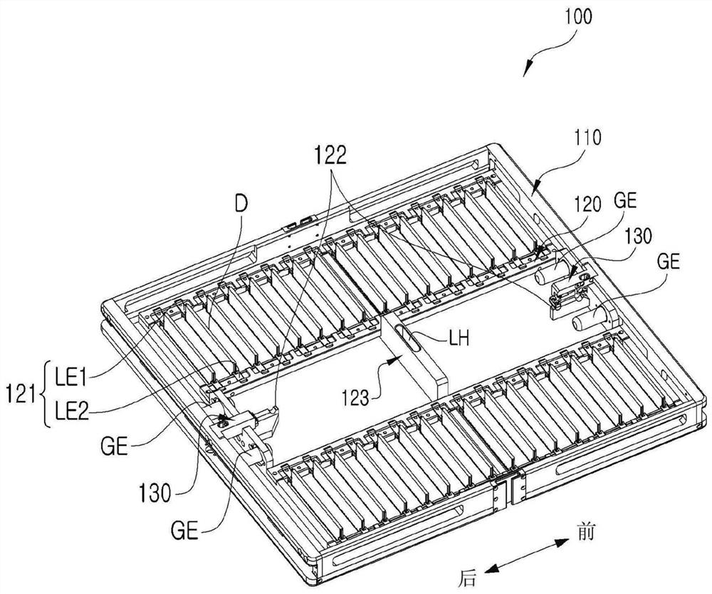
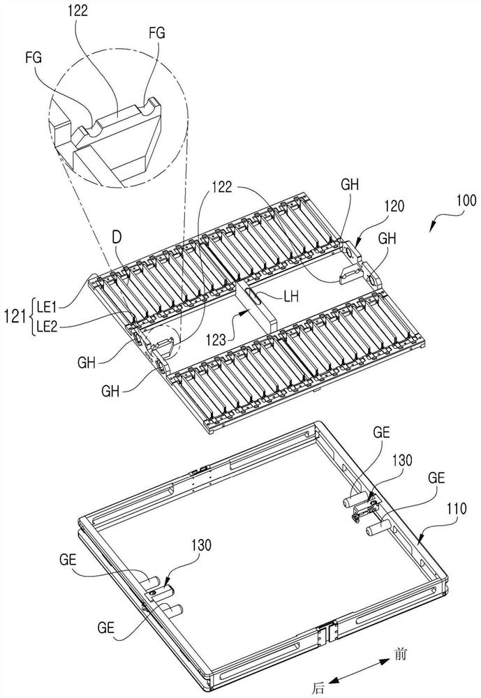
[0054] figure 1 is a perspective view of a test tray 100 according to the present invention, figure 2 its about figure 1 An exploded perspective view of the test tray 100 of FIG.

[0055] Such as figure 1 and figure 2 As shown, the test tray 100 includes an outer frame 110 , a loading frame 120 and a pair of holders 130 .

[0056] The outline frame 110 determines the outline size of the test tray 100 . Furthermore, a loading frame 120 and a holder 130 are provided on the outer frame 110 . Such an outline frame 110 is equipped with four guides GE for guiding the movement of the loading frame 120 and supporting the loading frame 120 .

[0057] The four guides GE each const...


PUM


Abstract

The present invention relates to a test tray and a sorter for testing electronic components, which are used in testing electronic components. According to the test tray and the sorting machine for electronic component testing of the present invention, in order to move the electronic components in stages in the test area, the test tray is equipped with a separate movable loading frame for loading electronic components, and the sorting machine is configured for Step-by-step support for mobile loading frames. According to the present invention, it is possible to minimize the reduction in processing capacity even when the electronic component to be tested becomes high-specification or becomes large in size, and at the same time, it is possible to realize reuse of testers and reduce resource waste or cost burden. Effect.

Description

technical field [0001] The present invention relates to a test tray used in the testing of electronic components and a sorter for electronic component testing which moves the corresponding test tray and supports the testing of electronic components. Background technique [0002] Electronic components such as semiconductor components produced are classified into good and bad after being tested by a testing machine, and only good products are shipped. [0003] The electrical connection between the testing machine and the electronic components is realized by a sorting machine for testing electronic components (hereinafter, simply referred to as a "sorting machine"). [0004] Generally, a sorter is manufactured in various forms according to various types of electronic components to be tested. Such sorting machines can be roughly divided into whether to apply test trays or not. [0005] Some types of sorting machines have a structure in which electronic components are directly ...

Claims


Application Information

Patent Timeline
Patent Type & Authority Patents(China)
IPC IPC(8): B07C5/34B07C5/02B07C5/00
CPCB07C5/34B07C5/02B07C5/00
Inventor 罗闰成尹圹熙
Owner TECHWING CO LTD
Learn More