Dehumidifier

A technology for dehumidifiers and accessories, applied in mechanical equipment, separation methods, heating methods, etc., can solve the problems of condensate water contaminating the periphery of the dehumidifier and dehumidifier, the dehumidifier is not easy to use, and the condensate water leaks, etc., and achieves a small number of parts. , the effect of minimizing damage and the possibility of condensate leakage

Pending Publication Date: 2020-03-03
LG ELECTRONICS INC
View PDF3 Cites 0 Cited by
  • Summary
  • Abstract
  • Description
  • Claims
  • Application Information

AI Technical Summary

Problems solved by technology

[0007] However, as described above, in a dehumidifier having a branch pipe and a drain pump in the discharge pipe, leakage of condensed water may occur at the junction of the branch pipe and the discharge pipe, or the junction of the branch pipe and the extension pipe, in which case leaking condensate may contaminate the interior of the dehumidifier or the surroundings of the dehumidifier
[0008] In addition, since the discharge pipe is connected to the lower part of the water storage part, when the discharge pipe or the extension pipe is not used, it is necessary to use a plug to close the discharge pipe or the extension pipe respectively, and to install a check valve in the discharge pipe, resulting in a large number of parts , the dehumidifier is not easy to use when the user loses the plug

Method used


Image

  • Dehumidifier
  • Dehumidifier
  • Dehumidifier

Examples


Embodiment Construction

[0050] Hereinafter, specific embodiments of the present invention will be described in detail with reference to the accompanying drawings.

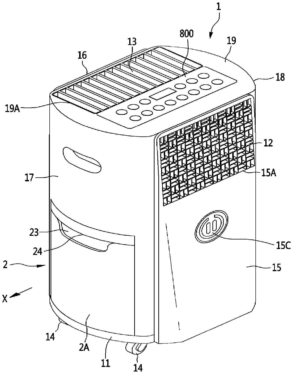
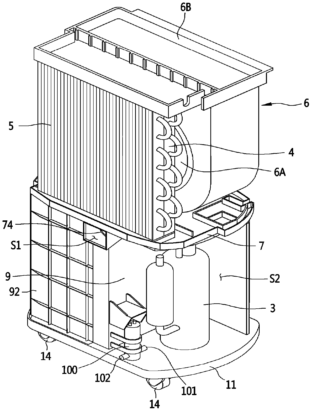
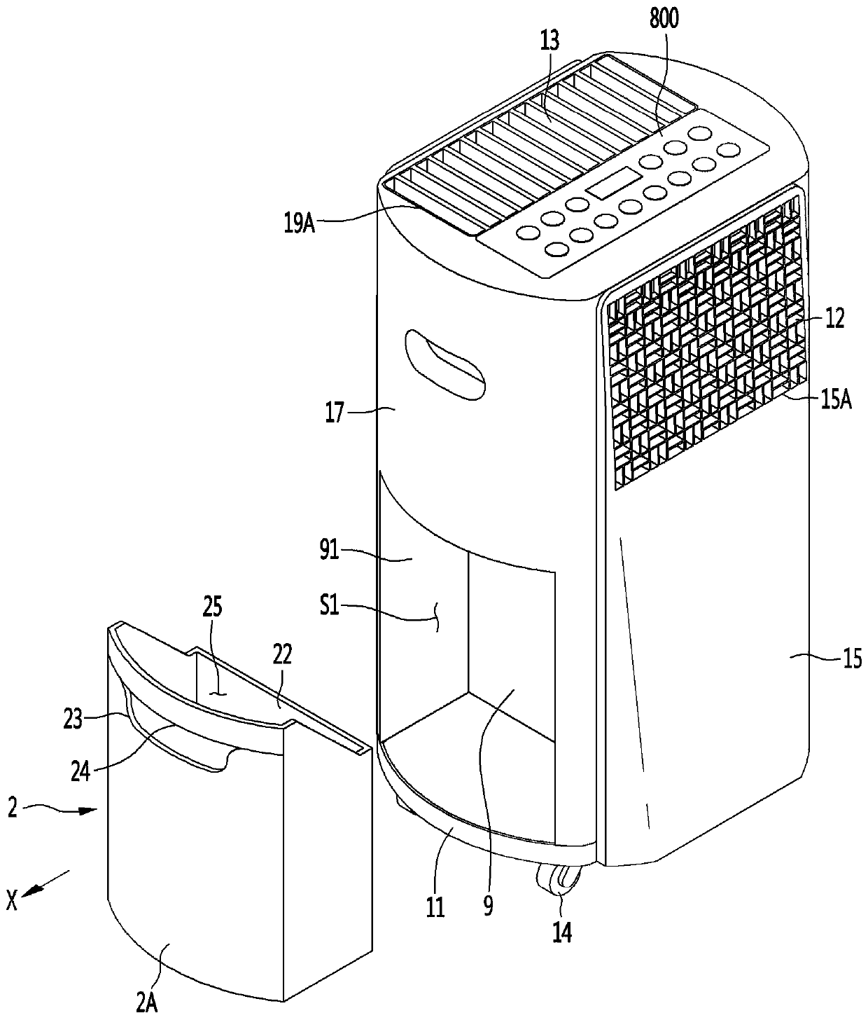
[0051] figure 1 is a perspective view showing a dehumidifier according to an embodiment of the present invention, figure 2 is a perspective view showing the inside of a dehumidifier according to an embodiment of the present invention, image 3 will be figure 1 The perspective view when the bucket is led out of the dehumidifier shown, Figure 4 will be figure 1 Side view of the dehumidifier with the pail shown leading out of the dehumidifier, Figure 5 is the drain hose connected to the figure 1 The three-dimensional view of the dehumidifier shown, Image 6 is the outer tube connected to the figure 1 Perspective view of the dehumidifier shown.

[0052] The dehumidifier may include: a housing 1 forming an appearance; and a bucket 2 detachably mounted on the housing 1 .

[0053]

[0054] The casing 1 may be composed of a combinat...


PUM


Abstract

A dehumidifier is provided that may include a bucket; a drain pan comprising a drain passage configured to guide condensed water dropped from an evaporator to the bucket; a pump; a barrier configuredto define a bucket space in which the bucket is accommodated; and a pump water inlet line and a pump water outlet line, which are connected to the pump. The pump water inlet line may include a flexible tube a portion of which is inserted into the bucket. The bucket may have an opening into which a portion of the flexible tube may be inserted. A portion of the flexible tube may be bent to be easilyinserted into the bucket through the opening of the bucket.

Description

technical field [0001] The present invention relates to a dehumidifier, and more particularly to a dehumidifier having a bucket into which condensed water condensed in an evaporator is accommodated. Background technique [0002] A dehumidifier is an air conditioning device used to reduce humidity. [0003] A dehumidifier can dehumidify a room using a refrigeration cycle device including a compressor, a condenser, an expansion mechanism, and an evaporator, and the dehumidifier can include: a drain pan to receive condensed water falling from the evaporator; The condensate that falls from the pan is contained in the pail. [0004] When condensed water accumulates in the pail, the user can remove the pail from the dehumidifier, discard the condensed water in the pail, and put the pail back into the dehumidifier. [0005] On the other hand, the dehumidifier can connect an additional outlet line to the drain pan, and install a drain pump in the outlet line, so that the condensed...

Claims


Application Information

Patent Timeline
Patent Type & Authority Applications(China)
IPC IPC(8): F24F3/14F24F5/00F24F11/89F24F13/22
CPCF24F3/1405F24F5/001F24F11/89F24F13/222B01D53/265B01D2259/4508F24F2003/144F24F2003/1446F24F13/20F24F2013/227F24F1/0083
Inventor 尹相俊金昌勋朴东民尹相渊
Owner LG ELECTRONICS INC
Why Eureka
Try Eureka