Reinforcement production line for prefabricated bottom plate of large-span laminated slab

A laminated board, large-span technology, applied in the online network, applications, household appliances, etc., can solve the problems of low efficiency, delay in working hours, and inability to tie together, etc., to achieve the effect of convenient welding, easy removal, and good consistency

Pending Publication Date: 2020-03-06
怀化四维建筑科技有限公司
View PDF0 Cites 2 Cited by
  • Summary
  • Abstract
  • Description
  • Claims
  • Application Information

AI Technical Summary

Problems solved by technology

[0003] However, due to the lack of corresponding steel bar bending equipment for cast-in-place prefabricated slabs, workers can only use simple tools to perform bending processing. On the one hand, they can only bend a small part of the steel bars at a time, which is extremely inefficient , the labor cost increases. On the other hand, because it is not a one-time processing, the bending degree and size of each part are not uniform. When the cage is tied together in the later stage, it cannot be tied together or it is very laborious, which will inevitably delay part of the working hours. Therefore, in order to adapt to With the current development trend of assembly buildings, it is necessary to develop a relatively high-efficiency bar-making production line

Method used


Image

  • Reinforcement production line for prefabricated bottom plate of large-span laminated slab
  • Reinforcement production line for prefabricated bottom plate of large-span laminated slab
  • Reinforcement production line for prefabricated bottom plate of large-span laminated slab

Examples


Embodiment Construction

[0032] In order to enable those skilled in the art to better understand the technical solution of the present invention, the present invention will be described in detail below in conjunction with the accompanying drawings. The description in this part is only exemplary and explanatory, and should not have any limiting effect on the protection scope of the present invention. .

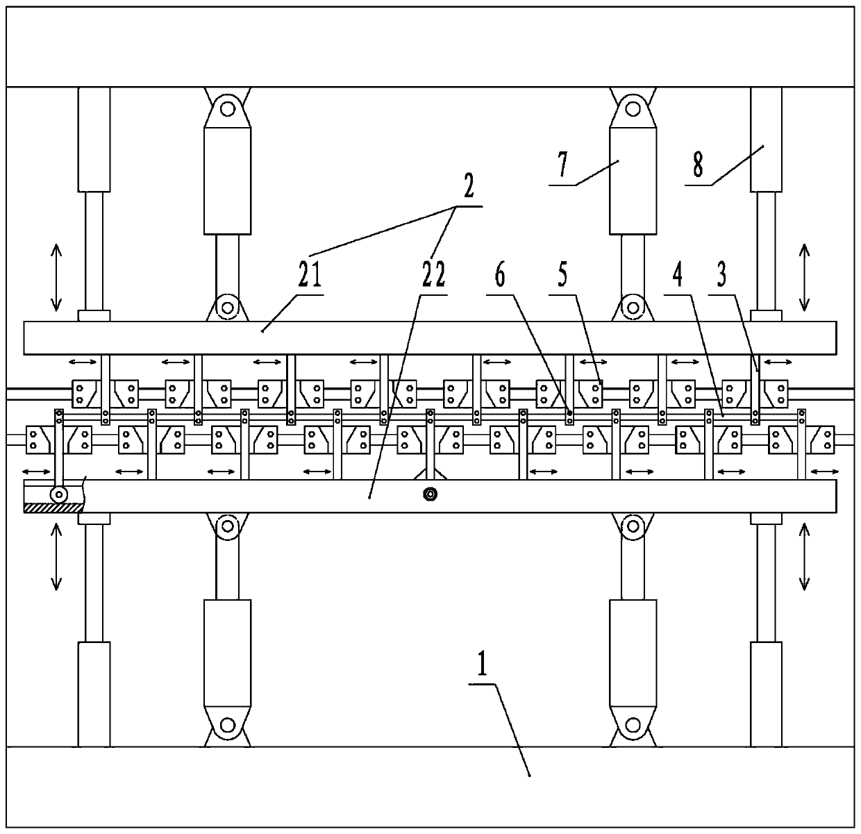
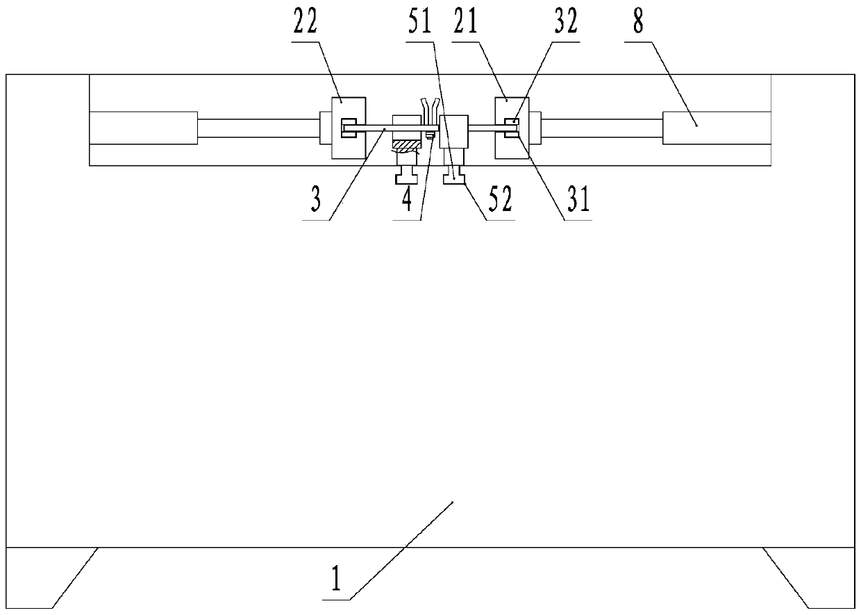
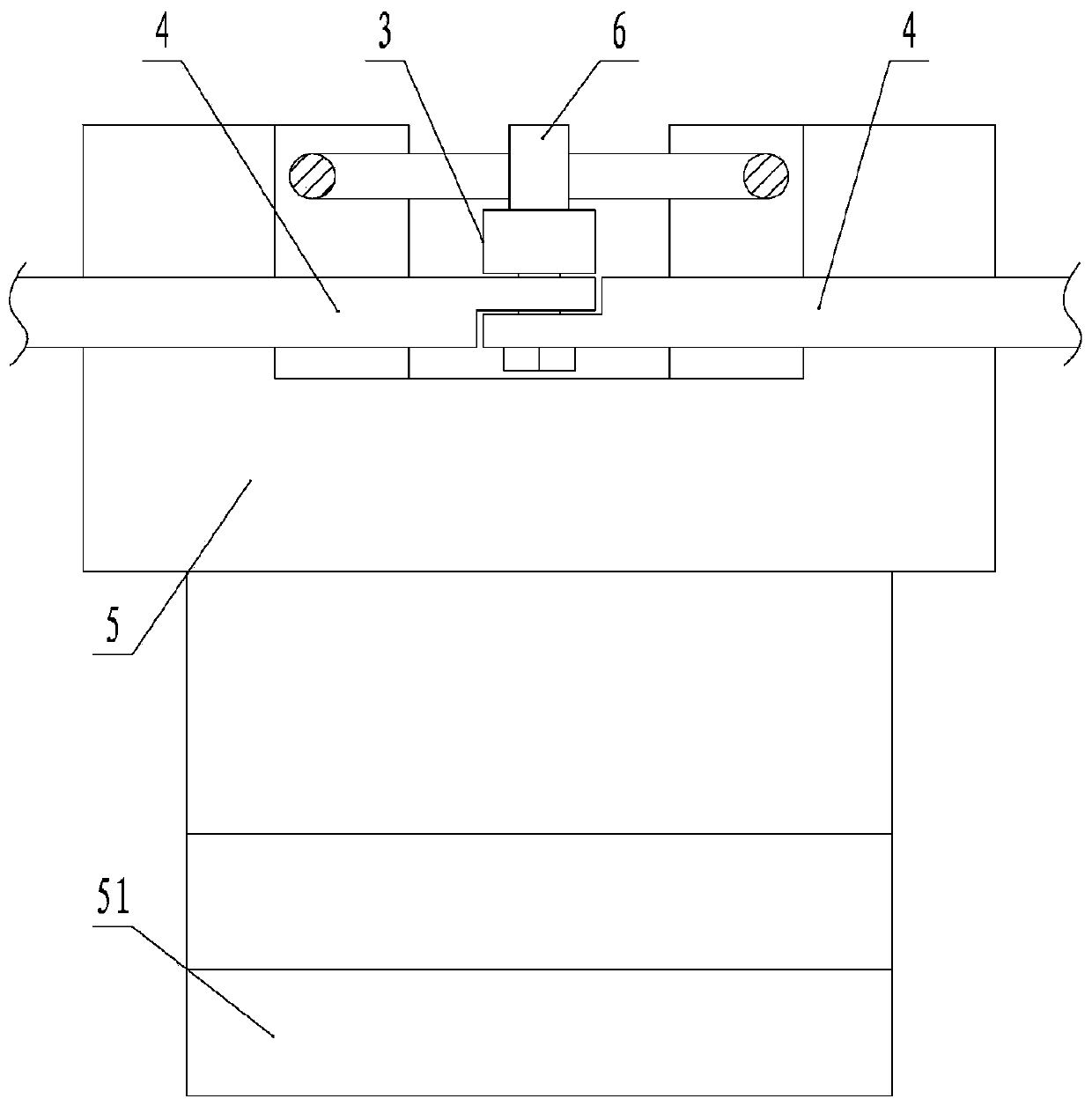
[0033] Such as Figure 1-11 As shown, the specific structure of the present invention is: a prefabricated floor reinforcement production line for large-span laminated slabs, comprising reinforcement equipment, a welding reinforcement device, and a reinforcement platform. The reinforcement equipment includes a body 1, and the body 1 A movable splint 2 is arranged horizontally opposite, and the splint 2 includes a first splint 21 and a second splint 22 parallel to each other. The first splint 21 and the second splint 22 move close to and away from at the same speed at the same time; the first splint 21, ...


PUM


Abstract

The invention discloses a reinforcement production line for a prefabricated bottom plate of a large-span laminated slab. The reinforcement production line comprises a reinforcement manufacturing device, a reinforcement welding device and a reinforcement binding platform, wherein the reinforcement manufacturing device comprises a machine body; clamping plates are horizontally and oppositely arranged on the machine body; the clamping plates comprise a first clamping plate and a second clamping plate; pull rods are arranged on the side walls, which are relatively close to each other, of the firstclamping plate and the second clamping plate; the other sides of the first clamping plate and the second clamping plate are connected with the machine body through telescopic mechanisms capable of horizontally moving; one ends of the pull rods are movably connected to the inner walls of the first clamping plate and the second clamping plate correspondingly; clamping mechanisms are arranged at theother ends of the pull rods; the plurality of pull rods on the first clamping plate and the plurality of pull rods on the second clamping plate are arranged in a staggered and spaced mode; the ends,provided with the clamping mechanisms, of every two adjacent pull rods are hinged through connecting rods with equal length; the section of the reinforcement welding device is an inverted-V-shaped welding frame; the reinforcement binding platform is square; and limiting grooves are formed in the upper end of the periphery of the reinforcement binding platform at equal intervals. The invention aimsto bend a steel bar into a continuous V shape at one time through the production line, so that subsequent reinforcement manufacturing and cage binding are facilitated, and the efficiency is improved.

Description

technical field [0001] The invention belongs to the technical field of construction machinery, in particular to a reinforcement production line for a prefabricated bottom plate of a large-span laminated plate. Background technique [0002] The laminated slab (that is, the laminated floor) is an assembled integral floor slab composed of prefabricated slabs and cast-in-place reinforced concrete layers. The laminated slab has good integrity and the upper and lower surfaces of the slab are flat, which is convenient for decoration of the decorative layer. It is suitable for the overall High-rise buildings and large-bay buildings with high rigidity requirements. The prefabricated slab is not only one of the components of the floor structure, but also a permanent formwork for the cast-in-place reinforced concrete laminated layer. Horizontal equipment pipelines can be laid in the cast-in-place laminated layer. [0003] However, due to the lack of corresponding steel bar bending equ...

Claims


Application Information

Patent Timeline
Patent Type & Authority Applications(China)
IPC IPC(8): B21F27/12
CPCB21F27/121
Inventor 罗芝棠甘立华
Owner 怀化四维建筑科技有限公司
Why Eureka
Try Eureka