
A Method for Predicting Dynamic Changes of Carbon Dioxide Drive Gas Front

A dynamic change, carbon dioxide technology, applied in the fields of carbon dioxide flooding to enhance oil recovery and dynamic prediction of gas fronts, can solve the problems such as the large gap between the predicted results and the actual situation, the high cost of gas tracer testing, and the large workload. Data collection and processing simple effects

Active Publication Date: 2021-07-23
XI'AN PETROLEUM UNIVERSITY
View PDF0 Cites 0 Cited by
  • Summary
  • Abstract
  • Description
  • Claims
  • Application Information

AI Technical Summary

Problems solved by technology

Among them, the theoretical calculation method usually does not consider the heterogeneity of the formation, and assumes that the gas is propelled in a two-dimensional radial flow similar to a cylinder. Due to the lack of considerations, the prediction results are far from the actual situation; the reservoir numerical simulation method The position of the gas drive front can be predicted in real time, but the accuracy of the prediction results depends on the accuracy of the geological model. The multi-solution of the simulation results often lacks strong constraints. At the same time, geological modeling and simulation calculations need to collect and process a large amount of oil. Reservoir static and production dynamic data not only require high data accuracy, but also have a large workload; the gas tracer method can quantitatively calculate the position of the gas drive front, but it can only obtain and test the current position of the gas drive front, and the It is impossible to predict the change of the position of the gas drive front under different cumulative gas injection amounts. At the same time, the cost of gas tracer testing is high and the test cycle is long, so long-term continuous gas tracer testing is unrealistic

Method used


Image

  • A Method for Predicting Dynamic Changes of Carbon Dioxide Drive Gas Front
  • A Method for Predicting Dynamic Changes of Carbon Dioxide Drive Gas Front
  • A Method for Predicting Dynamic Changes of Carbon Dioxide Drive Gas Front

Examples


Embodiment Construction

[0050] The present invention will be further described below in conjunction with the accompanying drawings and embodiments.

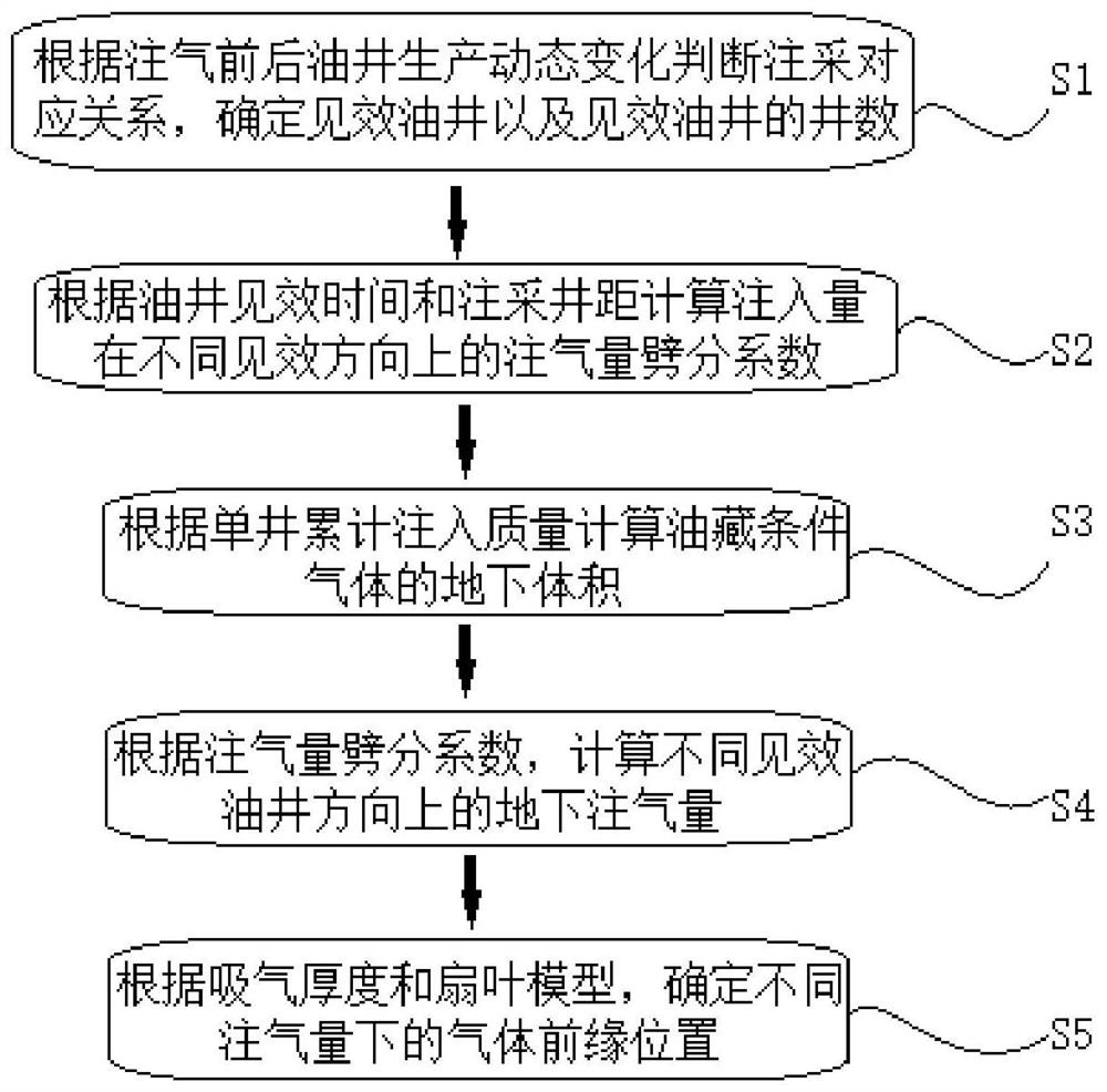
[0051] refer to figure 1 , The method for predicting the dynamic change of the carbon dioxide drive gas front of the present invention is a new method for predicting the dynamic change of the gas drive gas front position using the injection-production correspondence relationship of the suction profile test, the injection-production well spacing, and the oil well effect judgment. It mainly includes five parts: one is to judge the corresponding relationship between injection and production according to the production dynamic changes of oil wells before and after gas injection, and determine the effective oil wells and the number of effective oil wells; The third is to calculate the underground volume of reservoir-conditioned gas based on the cumulative injection quality of a single well; the fourth is to calculate the underground gas injection volume in d...


PUM


Abstract

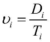
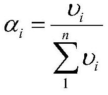
The invention relates to the technical field of carbon dioxide flooding enhanced oil recovery in oil and gas field development, and discloses a method for predicting the dynamic change of the carbon dioxide flooding gas front, including the following process: comprehensive suction profile results, injection-production well spacing and oil well effective judgment of injection-production correspondence Split the gas injection volume in different effective oil well directions, calculate the split coefficient of gas injection volume and the gas injection volume in different oil well directions according to the gas injection effective speed, and calculate the dynamics of the gas drive front position under different gas injection volumes with the fan blade model To realize the dynamic change prediction of carbon dioxide flooding gas front. The present invention only needs basic data such as production dynamic data, suction profile data, and injection-production well spacing, and data collection and processing are simple, and through dynamic prediction of the gas drive front, it is beneficial to grasp CO 2 The propulsion speed and predicted gas breakthrough time can be combined with the pressure profile to quantitatively calculate the dynamic change of the miscible range, which is the CO 2 Provide basis for dynamic tracking evaluation and optimization and adjustment of injection-production parameters.

Description

technical field [0001] The invention relates to the technical field of carbon dioxide flooding enhanced oil recovery in the development of oil and gas fields, in particular to the technical field of dynamic prediction of gas fronts, in particular to a method for predicting dynamic changes of carbon dioxide flooding gas fronts. Background technique [0002] Carbon dioxide flooding enhanced oil recovery and sequestration technology has been paid more and more attention as an effective method for resource utilization of greenhouse gases. Since the position of the gas front changes dynamically at any time during the gas drive process, the prediction of the gas front position becomes a difficult point in the tracking of the gas drive state. At present, the position of the gas front is usually expressed by the distance from the gas front to the gas injection well. Knowing the dynamic change of the position of the carbon dioxide flooding gas front is not only helpful for understand...

Claims


Application Information

Patent Timeline
Patent Type & Authority Patents(China)
IPC IPC(8): E21B43/16G06F30/20
CPCE21B43/164
Inventor 湛杰郑自刚张颖
Owner XI'AN PETROLEUM UNIVERSITY
Learn More