
Self-walking type hydraulic trestle

A self-propelled trestle technology, applied in the direction of pedestrian bridges, bridges, bridge forms, etc., can solve the problems of hydraulic trestle bridges, which are difficult, difficult to solve, and low work efficiency, so as to improve construction efficiency, simplify the process of adjusting the position, and simplify the construction process Effect

Inactive Publication Date: 2020-03-06
安徽豆智智能装备制造有限公司
View PDF0 Cites 7 Cited by
  • Summary
  • Abstract
  • Description
  • Claims
  • Application Information

AI Technical Summary

Problems solved by technology

[0002] At present, in the process of tunnel construction, it is often necessary to use the hydraulic trestle as a temporary road surface for vehicles to pass. The surface of the tunnel under the hydraulic trestle needs to be constructed and poured. It mainly includes the two steps of constructing arc-shaped inverted arches and constructing and filling on the inverted arches. In the prior art, these two steps are generally constructed separately. First, the inverted arch formwork is manually fixed on the hydraulic trestle, and the hydraulic trestle gradually When the tunnel stretches out and moves to make the inverted arch at the tail leak out, the construction and filling on this part of the inverted arch will result in low work efficiency
[0003] In addition, during the construction process, especially in curved positions such as tunnel turns, sometimes it is necessary to adjust the position of the inverted arch formwork horizontally to gradually realize the tunnel turning. Since the inverted arch formwork needs to be fixed by hydraulic trestles, this means that horizontal adjustment is required The position of the hydraulic trestle is already very difficult to move the huge and heavy hydraulic trestle alone. This problem becomes more difficult to solve when the position accuracy of the inverted arch formwork needs to be considered, which brings great challenges to the tunnel construction.

Method used


Image

  • Self-walking type hydraulic trestle
  • Self-walking type hydraulic trestle
  • Self-walking type hydraulic trestle

Examples


Embodiment Construction

[0029] In order to make the object, technical solution and advantages of the present invention clearer, the present invention will be further described in detail below in conjunction with specific embodiments and with reference to the accompanying drawings.

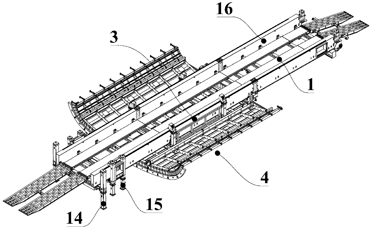
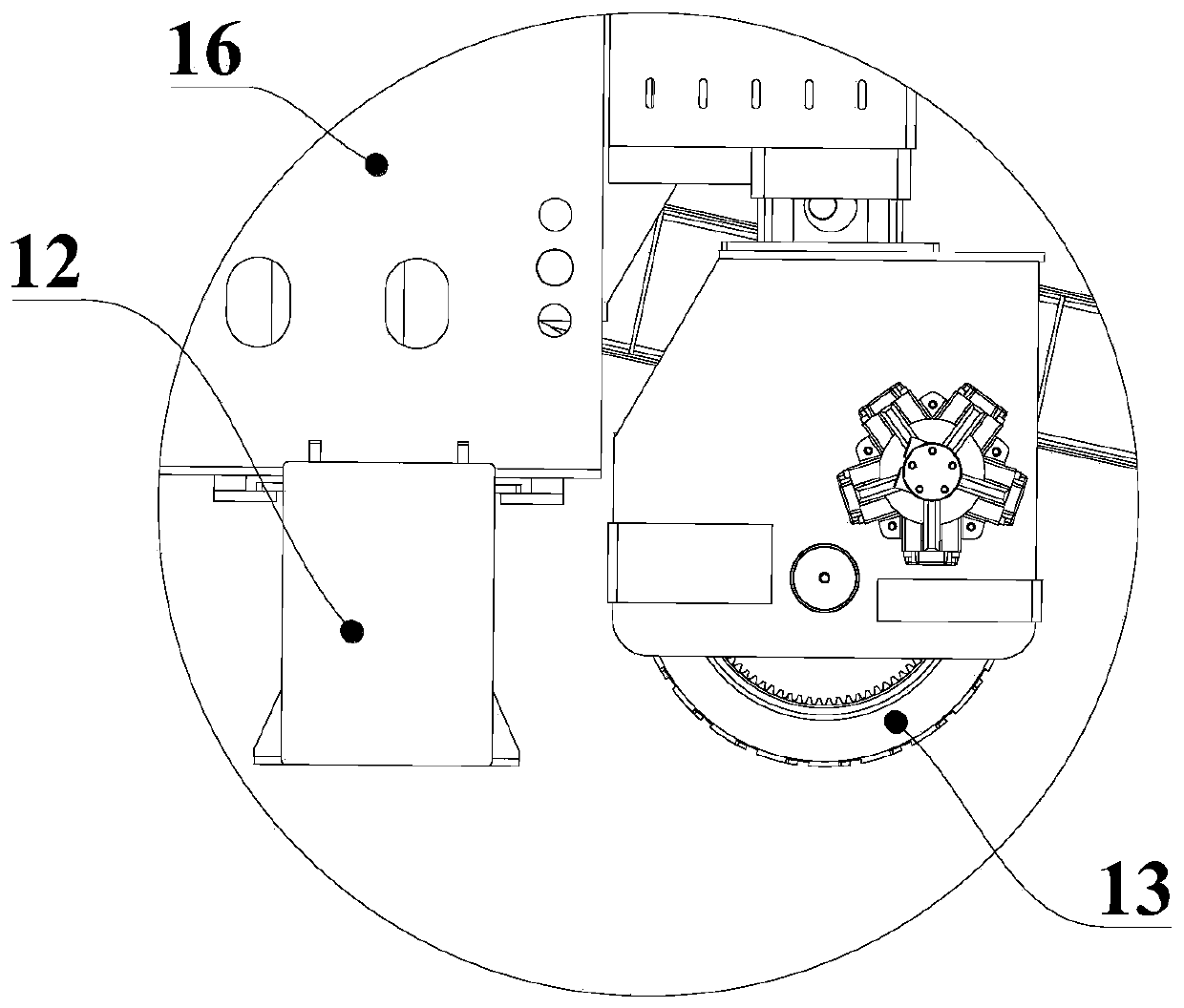
[0030] refer to figure 1 and figure 2 , the present embodiment provides a self-propelled hydraulic trestle, which includes a trestle main body 1 for vehicles to pass through. The two ends of the trestle main body 1 are respectively provided with slopes 11 hinged and fixed relative to the trestle main body 1. trestle body 1; combined image 3 and Figure 4 The two ends of the trestle main body 1 along the length direction are respectively provided with a first support leg 12 and a second support leg 14 which are in contact with the ground and support the trestle main body 1, and one end of the first support leg 12 is fixedly arranged on the trestle main body 1 There is a walking wheel 13 that can change the height rela...


PUM


Abstract

The invention provides a self-walking type hydraulic trestle. The self-walking type hydraulic trestle comprises a trestle main body for vehicle traffic, the two ends of the trestle main body are respectively provided with a first supporting leg and a second supporting leg, one end, close to the first supporting leg, of the trestle main body is provided with the first supporting leg is provided with a walking wheel which can change the height, one end, close to the second supporting leg, of the trestle main body is provided with a movable supporting leg which can move along the length directionof the trestle main body, the movable supporting leg can expand and retract to change the length; the first supporting leg and the second supporting leg can adjust the horizontal distances to the trestle main body; the bottom part of the trestle main body is provided with inverted arch formworks and filling formworks in a hanging manner, the inverted arch formworks and the filling formworks are arranged in sequence along the tunnel ground construction direction, and the inverted arch formworks and filling formworks can change the relative distances to the trestle main body in the vertical direction. The self-walking type hydraulic trestle has the advantages that the two ends of the trestle main body are provided with structures alternately contacting with a ground, so that the position adjustment is realized, and the inverted arch formworks and the filling formworks are arranged under the trestle main body, so that the construction efficiency is improved.

Description

technical field [0001] The invention relates to the technical field of tunnel construction, in particular to a self-propelled hydraulic trestle. Background technique [0002] At present, in the process of tunnel construction, it is often necessary to use the hydraulic trestle as a temporary road surface for vehicles to pass. The surface of the tunnel under the hydraulic trestle needs to be constructed and poured. It mainly includes the two steps of constructing arc-shaped inverted arches and constructing and filling on the inverted arches. In the prior art, these two steps are generally constructed separately. First, the inverted arch formwork is manually fixed on the hydraulic trestle, and the hydraulic trestle gradually When the tunnel stretches out and moves to make the invert at the tail leak out, the construction and filling on this part of the invert will result in low work efficiency. [0003] In addition, during the construction process, especially in curved positio...

Claims


Application Information

Patent Timeline
IPC IPC(8): E21F13/00E21D11/40E01D15/10
CPCE01D15/10E21D11/40E21F13/00
Inventor 陆利
Owner 安徽豆智智能装备制造有限公司
Learn More