Multi-magnetic circuit magnetorheological shock absorber with permanent magnets

A magneto-rheological shock absorber and permanent magnet technology, which is applied in the direction of shock absorbers, springs/shock absorbers, shock absorbers, etc. The volume of the vibrator is huge, etc.

A magneto-rheological shock absorber and permanent magnet technology, which is applied in the direction of shock absorbers, springs/shock absorbers, shock absorbers, etc. The volume of the vibrator is huge, etc.

CN110864068BActive Publication Date: 2021-09-14环形山(重庆)科技有限公司

Image

  • Multi-magnetic circuit magnetorheological shock absorber with permanent magnets
  • Multi-magnetic circuit magnetorheological shock absorber with permanent magnets
  • Multi-magnetic circuit magnetorheological shock absorber with permanent magnets

Examples


Embodiment Construction

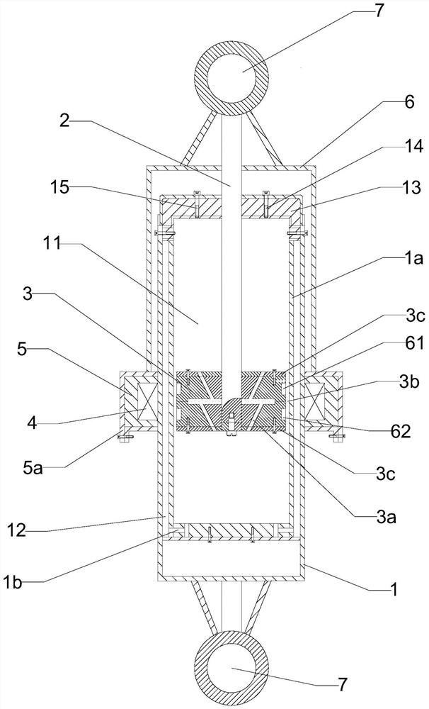
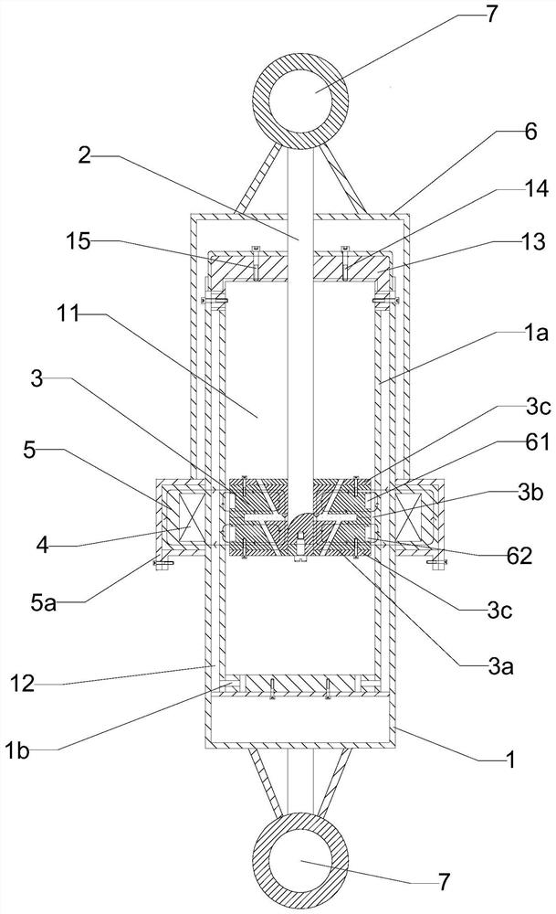
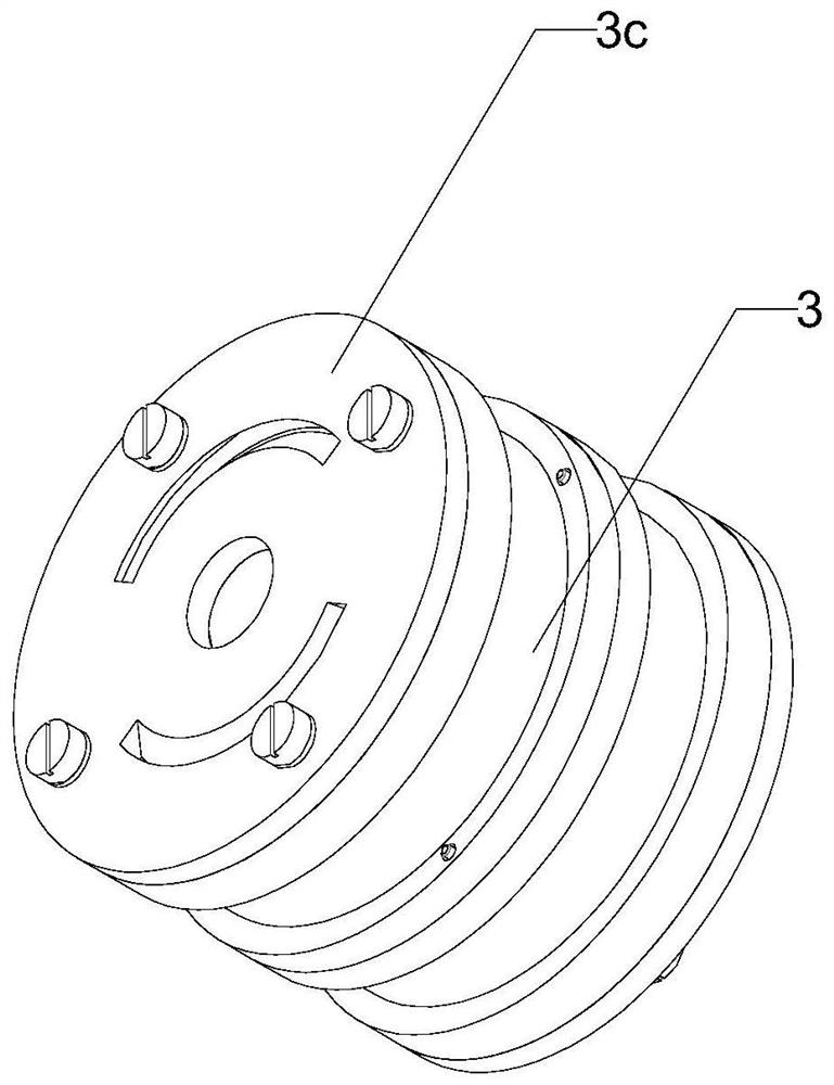
[0030] figure 1 It is a structural schematic diagram of the present invention, figure 2 It is a schematic diagram of the magnetic circuit of the present invention, image 3 It is the magnetic core assembly drawing of the present invention, Figure 4 The explosion diagram of the magnetic core of the present invention is shown in the figure. The multi-magnetic circuit magnetorheological shock absorber with permanent magnets in this embodiment includes a cylinder 1, a piston rod 2, a magnetic core 3, a magnetorheological fluid, and a coil 4. Magnetic conductor 5 and permanent magnet;

[0031] The cylinder body 1 is divided into a working chamber 11 and a compensation chamber 12 by the inner wall 1a, and the working chamber 11 communicates with the bottom of the compensation chamber 12;

[0032] Piston rod 2, the lower end is placed in the cylinder body 1, the upper end extends out of the cylinder body 1 along the piston hole on the upper end cover 13 of the cylinder body 1, a...


PUM


Abstract

The invention discloses a multi-magnetic circuit magneto-rheological shock absorber with permanent magnets, which includes a cylinder body, a piston rod, a magnetic core, a magnetorheological fluid, a coil, a magnetizer and a permanent magnet; The outside of the cylinder body facilitates the installation and disassembly of the coil during daily maintenance. At the same time, the heat generated when the coil is energized can be dissipated well without affecting the viscosity of the magneto-rheological fluid, thereby prolonging the service life of the shock absorber. Since the coil is placed outside, the internal structure of the shock absorber is relatively simple, thereby reducing manufacturing difficulty and saving manufacturing cost.

Description

technical field [0001] The invention relates to the field, in particular to a multi-magnetic circuit magneto-rheological shock absorber with permanent magnets. Background technique [0002] The viscosity of magnetorheological fluid can change with the strength of the external magnetic field, and its main characteristics are fast, reversible and controllable. The magnetorheological shock absorber uses this characteristic to change the output damping force of the magnetorheological hydraulic mount by controlling the current in the excitation coil to change the magnetic field strength, so as to attenuate the vibration of the car. This process responds quickly, the process is continuous, reversible. [0003] In the current magneto-rheological shock absorber, the coil is mainly arranged in the circumferential groove of the piston, and the coil wire is led out of the shock absorber through the deep hole processed in the piston rod. Although this solution has a compact structure,...

Claims


Application Information

Patent Timeline
14 Sep 2021
Publication
CN110864068B
IPC
F16F9/53; F16F9/32
CPC
F16F9/3207; F16F9/535
Inventors
邓召学; 韦鑫鑫