

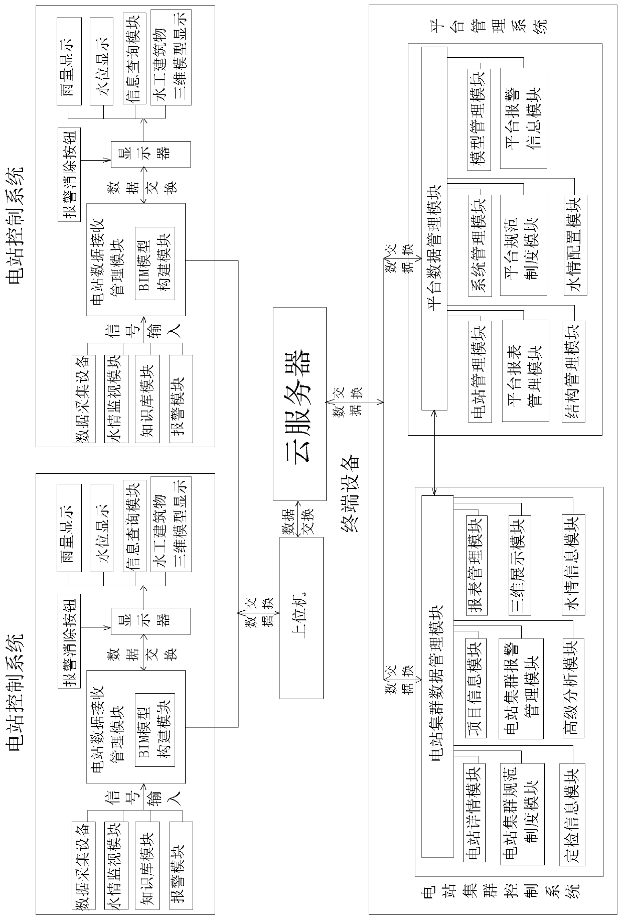
Hydraulic engineering monitoring system based on three-dimensional display
A technology of three-dimensional display and monitoring system, which is applied in general control system, control/regulation system, forecasting, etc., and can solve problems such as inability to intuitively and visually display the safety status of hydraulic structures
- Summary
- Abstract
- Description
- Claims
- Application Information
AI Technical Summary
Problems solved by technology
Method used
Image

Examples
Embodiment 1
[0123] Embodiment 1 Association analysis of safety monitoring data
[0124] (1) Combing and analysis of safety monitoring data
[0125] For dam safety monitoring data (such as dam deformation, seepage pressure, seepage volume, earth pressure, etc.), carry out preprocessing work before analysis, mainly to clean and verify the data, delete duplicate information in the data, and correct Existing errors ensure data consistency and remove white noise in blank data domains and knowledge backgrounds.
[0126] According to the project requirements, divide the preprocessed safety monitoring data into different data sub-items, and divide the monitoring data into sub-items according to the type of monitoring data for each category of data, and divide the data in each sub-item Preliminary sorting is carried out in the form of time series from far to near.
[0127] After the preliminary sorting, the data were subjected to exploratory data analysis (EDA), and the basic attributes and dist...
Embodiment 2
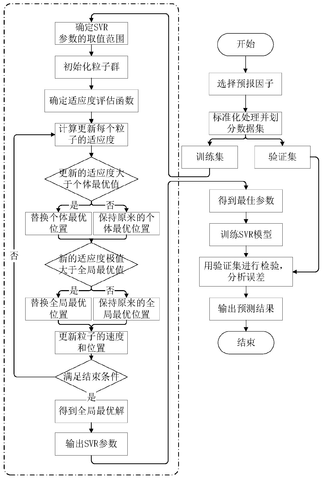
[0148] Embodiment 2 The dam safety performance intelligent prediction model based on SVR is constructed, such as figure 2 shown
[0149] (1) Selection of predictors
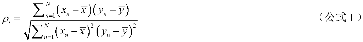
[0150] Based on the optimal forecast period determined in embodiment 1, according to the correlation coefficients of each monitoring data item and the safety performance index on this forecast period, the correlation coefficients are arranged in order from large to small, and analyzed in pairs Monitor the correlation between data items, remove one of the two with a cross-correlation coefficient greater than 0.4, and use the selected monitoring data item as the final selection predictor.
[0151] (2) Construction of PSO-SVR model
[0152] The particle swarm optimization algorithm is used to search for the optimal solution of the parameters C, σ and ε of the SVR, and the construction steps of the model are shown in the figure. The specific steps are:
[0153] Step1-determine the predictor;
[0154] Step2- Org...
PUM
 Abstract
Description
Claims
Application Information