Medical interventional needle assembly and medical interventional catheter

An interventional, needle assembly technology, applied in the field of medical devices, can solve problems such as fluid scouring fracture, increased perfusion pressure, line fracture, etc., to prevent discounts or fractures, reduce perfusion pressure, and increase strength and toughness.

Active Publication Date: 2020-03-10
SHANGHAI MICROPORT EP MEDTECH CO LTD
View PDF10 Cites 5 Cited by
  • Summary
  • Abstract
  • Description
  • Claims
  • Application Information

AI Technical Summary

Problems solved by technology

[0004] In the prior art, the temperature sensor line and the radio frequency wire extend from the far end to the proximal end in the saline tube, occupying the space of the saline tube, which is likely to cause a decrease in the saline perfusion flow rate or an increase in the perfusion pressure
Moreover, both the temperature sensor line and the temperature sensing point of the temperature sensor are placed inside the needle, and are fixed or not fixed with glue, which will cause the glue to fall off or the contact point of the temperature sensor to be separated from the inner wall of the needle, resulting in the temperature sensor not being able to accurately sense the temperature, and the saline solution being perfused. During the process, the RF wires and temperature sensor wires will be washed continuously, and the RF wires or temperature sensor wires are not restrained in the saline pipe, so there is a risk of wire breakage
[0005] On the other hand, the existing connection method between the ablation needle and the catheter is that the ablation needle is set inside the catheter, so that the area where the ablation needle is connected to the catheter cannot perform the ablation function, and if this area is reduced as much as possible, it may cause both The connection is not firm, and there are safety hazards such as loosening
[0006] For other similar medical interventional needle assemblies, the above-mentioned problems also exist, such as interventional myocardial injection needles, etc. In order to accurately locate the injection position, a magnetic positioning sensor can be set at the injection needle, and the electric wire of the magnetic positioning sensor There will also be problems such as being easily broken by fluid washing or the magnetic positioning sensor is separated from the injection needle.

Method used


Image

  • Medical interventional needle assembly and medical interventional catheter
  • Medical interventional needle assembly and medical interventional catheter
  • Medical interventional needle assembly and medical interventional catheter

Examples


Embodiment 1

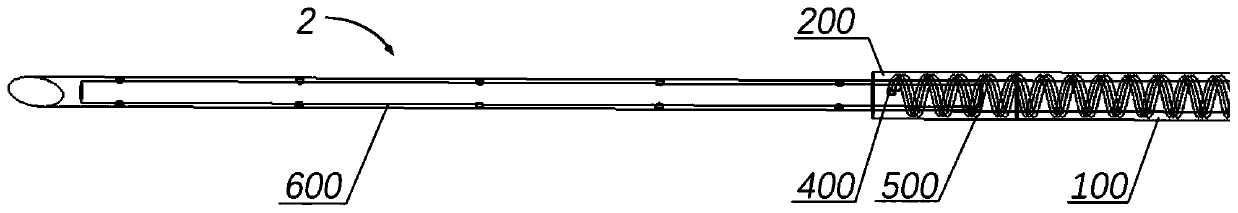
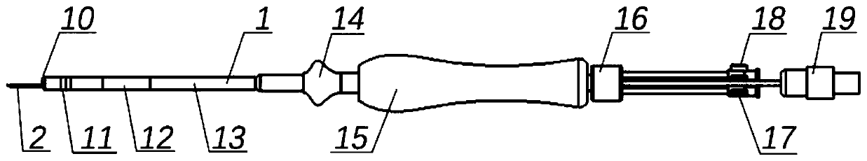
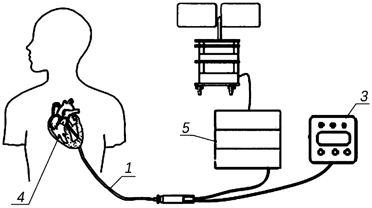
[0055] Please refer to Figure 1 to Figure 3 ,in, figure 1 It is a schematic diagram of the perfusion ablation needle assembly provided by Embodiment 1 of the present invention, figure 2 It is an overall schematic diagram of the perfusion ablation catheter provided by Embodiment 1 of the present invention, image 3 It is a schematic diagram of the use of the perfusion ablation catheter provided by Embodiment 1 of the present invention.

[0056] Such as Figure 2 to Figure 3 As shown, Embodiment 1 of the present invention provides a perfusion ablation catheter, which includes: a catheter body 1 and a perfusion ablation needle assembly 2 , the catheter body 1 has a first inner cavity penetrating in the axial direction, and the perfusion ablation needle assembly 2 is movably installed in the first inner cavity. In an exemplary example, the catheter body 1 includes: a head electrode 10 , a ring electrode 11 , a bendable section 12 , a main body section 13 , a push button 14 ,...

Embodiment 2

[0068] Please refer to Figure 4 ,in, Figure 4 It is a schematic diagram of the perfusion ablation needle assembly provided by the second embodiment of the present invention.

[0069] The perfusion ablation needle assembly and the perfusion ablation catheter of the second embodiment of the present invention are basically the same as the perfusion ablation needle assembly and the perfusion ablation catheter of the first embodiment, the same parts will not be described, and only the differences will be described below.

[0070] Such as Figure 4 As shown, different from the first embodiment, a part of the galvanic wire 400 also penetrates into the ablation needle 600 and is attached to the inner surface of the ablation needle 600, and the temperature sensor is also attached to the inner surface of the ablation needle 600. on the inner surface of the ablation needle 600 . Specifically, the galvanic couple wire 400 passes inwardly from the tube wall of the second tube section ...

Embodiment 3

[0072] Please refer to Figure 5 with Image 6 ,in, Figure 5 is a schematic diagram of the perfusion ablation needle assembly provided in Embodiment 3 of the present invention, Image 6 yes Figure 7 Axial cross-sectional view of the perfusion ablation needle assembly shown.

[0073] The perfusion ablation needle assembly and the perfusion ablation catheter of the third embodiment of the present invention are basically the same as the perfusion ablation needle assembly and the perfusion ablation catheter of the first embodiment, the same parts will not be described, and only the differences will be described below.

[0074] Such as Figure 5 with Image 6 As shown, the perfusion ablation needle assembly 2 provided in the third embodiment also includes a third tube segment 300; the outer diameter of the second tube segment 200 is smaller than the outer diameter of the first tube segment 100, and the distal end of the third tube segment 300 is connected to The proximal en...


PUM


Abstract

The invention provides a medical interventional needle assembly and a medical interventional catheter. The medical interventional needle assembly comprises a first tube section, a second tube section,an electric lead and a metal needle, the second tube section is connected to the far end of the first tube section, the metal needle is arranged on the second tube section, and at least one part of the electric lead is woven and formed in the tube wall of the first tube section. Due to the configuration, the electric lead woven and formed in the pipe wall of the first pipe section does not influence the internal space of the first tube section, so that the flow of saline water is ensured, the perfusion pressure is reduced, and the risk that the electric lead is scoured by the saline water tobe broken is also avoided. In addition, the electric lead is woven into the pipe wall, so that the strength and toughness of the pipe can be improved and the pipe is prevented from being bent or broken.

Description

technical field [0001] The invention relates to the technical field of medical devices, in particular to a medical intervention needle assembly and a medical intervention catheter. Background technique [0002] Radiofrequency (RF) ablation of the heart and other tissues is a well known method for creating a thermal lesion at the tip of the electrode. Tissue heated above a threshold of about 50 to 55° C. in the ablated area is irreversibly damaged, thereby achieving the effect of ablation. Direct resistive heating of a small area at the electrode-tissue interface is the main source of heat in radiofrequency ablation. Energy absorption is related to the square of the current density and inversely proportional to tissue conductivity. In addition, heat conduction is another source of ablation energy. Hypertrophic cardiomyopathy reduces the amount of blood the heart pumps throughout the body, eventually leading to heart failure; at the same time, lesions in the hypertrophic hear...

Claims


Application Information

Patent Timeline
Patent Type & Authority Applications(China)
IPC IPC(8): A61B18/12A61B18/14
CPCA61B18/12A61B18/1477A61B18/1492A61B2018/00011A61B2018/00178A61B2018/00351A61B2018/00577A61B2018/00791A61B2018/00821A61B2018/1425A61B2562/221
Inventor 梁波蒋佳强奚云珠赵乾成孙毅勇
Owner SHANGHAI MICROPORT EP MEDTECH CO LTD
Why Eureka
Try Eureka