High-precision heavy-load carrying operation device

A kind of operation equipment and high-precision technology, which is applied in the direction of transportation and packaging, load suspension components, running mechanism, etc., can solve the problems of complex manufacturing, installation process, high cost and rising cost, and achieve the effect of wide operation area

Pending Publication Date: 2020-03-10
湖南天桥嘉成智能科技有限公司
View PDF7 Cites 4 Cited by
  • Summary
  • Abstract
  • Description
  • Claims
  • Application Information

AI Technical Summary

Problems solved by technology

[0002] At present, large-scale space transportation generally adopts solutions such as manual transportation by cranes, automatic transportation by intelligent cranes, and truss manipulators. There is usually a problem of poor positioning accuracy when handling materials by cranes or intelligent cranes; when truss manipulators have large-scale material handling High cost, especially when the load is heavy, the cost rises sharply, and the manufacturing and installation processes are complicated

Method used


Image

  • High-precision heavy-load carrying operation device
  • High-precision heavy-load carrying operation device
  • High-precision heavy-load carrying operation device

Examples


Embodiment 1

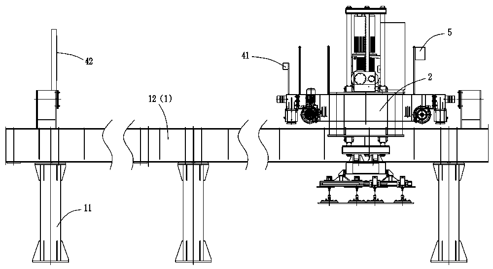
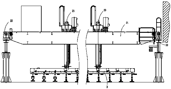
[0028] Such as figure 1 with figure 2 As shown, a high-precision heavy-duty handling operation equipment is provided, which includes a frame part 1, a moving part 2, a clamp part 3 and an electrical control system. The frame part includes a plurality of columns 11 arranged on both sides of the moving part. It can be extended and arranged according to the transportation distance. A girder 12 is erected between the adjacent columns 11 on each side to carry the load of the moving part. The girders are connected by bolts, and the rails 13 are laid on the girders; The bridge frame 21 between the side rails 13, the bridge frame 21 is driven by the first traveling mechanism 22 to walk along the track 13 (the track direction is hereinafter referred to as the X-axis direction); A lifting mechanism 23 that moves straight (the lifting direction of the lifting mechanism is hereinafter referred to as the Z-axis direction), and the gripper part 3 is connected to the lifting mechanism 23 f...

Embodiment 2

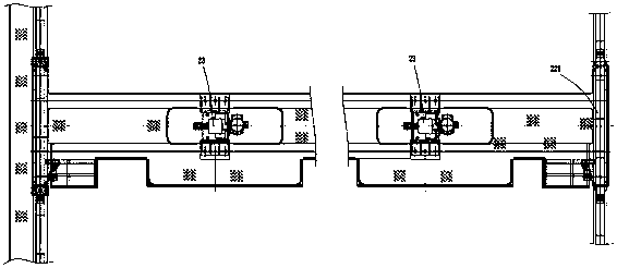
[0038] In this embodiment, on the basis of Embodiment 1, a function is added to enable the lifting mechanism to drive the clamp part to walk in the length direction of the bridge. Specifically, the bridge 21 includes two sub-bridges 211 arranged in parallel and with spacing. Two trolleys 212 are straddled, the lifting mechanism is set on the trolley, the sub-bridge is provided with a walking track 213 along its own length, and the trolley is equipped with a second traveling mechanism to drive the trolley to slide along the running track (this direction is called the Y-axis direction ), in order to realize the movement of the operating equipment in the directions of X, Y, and Z axes, the second traveling mechanism includes a motor 214 and a bridge traveling wheel 215, that is, the walking of the trolley is realized simply by referring to the motor-driven traveling wheel in the prior art , so I won’t make too many records here.

[0039] In this embodiment, each trolley is provid...


PUM


Abstract

The invention relates to the technical field of carrying work, and discloses a high-precision heavy-load carrying operation device. The high-precision heavy-load carrying operation device comprises aframe part, a moving part, a clamp part and an electric control system, the frame part comprises stand columns arranged on the two sides of the moving part; a girder is arranged between every two adjacent stand column, a rail is laid on the girder, the moving part comprises a bridge frame spanning between the two side rails, the bridge frame is driven by a first walking mechanism to walk along therail; the moving part further comprises a lifting mechanism arranged on the bridge frame to move vertically, and the clamp part is connected to the lifting mechanism; one end of the moving part is provided with a laser ranging sensor, the frame part is provided with a laser reflecting plate corresponding to the laser ranging sensor at the end position of the rail, and the first walking mechanism,the lifting mechanism and the laser ranging sensor are all in signal connection with the electrical control system. The overall framework of the equipment is suitable for large-range material carrying, the operation area is wider, the walking distance is not limited, the maximum span is more than 20 m, the maximum load is more than or equal to 50 t, and the equipment carrying precision is smallerthan or equal to + / -5 mm.

Description

technical field [0001] The invention relates to the technical field of handling operations, in particular to a high-precision heavy-duty handling operation equipment. Background technique [0002] At present, large-scale space transportation generally adopts solutions such as manual handling by cranes, automatic handling by intelligent cranes, and truss manipulators. There is usually a problem of poor positioning accuracy when handling materials by cranes or smart cranes; when truss manipulators have large-scale material handling The cost is high, especially when the load is heavy, the cost rises sharply, and the manufacturing and installation processes are complicated. The positioning accuracy of the existing intelligent crane material handling is usually ≥±20mm, the span of the truss manipulator is usually ≤12m, and the load is ≤2t. Contents of the invention [0003] The technical problem solved by the present invention is to overcome the defects of the prior art, and p...

Claims


Application Information

Patent Timeline
Patent Type & Authority Applications(China)
IPC IPC(8): B66C9/00B66C13/16B66C13/22
CPCB66C9/00B66C13/16B66C13/22
Inventor 查铂毛轩昂郑祎殷卓华廖济红尹施南
Owner 湖南天桥嘉成智能科技有限公司
Why Eureka
Try Eureka