Spin-type air filter device

An air filter, spin-type technology, applied in the direction of fuel air filter, combustion air/combustion-air treatment, charging system, etc., can solve the problems of shortened filter life, manual cleaning, airflow impact damage, etc. To achieve the effect of long service life, prolonging service life and reducing service life

Pending Publication Date: 2020-03-10
MANNHUMMEL FILTER SHANGHAI
View PDF0 Cites 2 Cited by
  • Summary
  • Abstract
  • Description
  • Claims
  • Application Information

AI Technical Summary

Problems solved by technology

[0002] At present, many air filter assemblies have the problem of reciprocating disassembly and assembly within the maintenance mileage, mainly to remove the dust adhering to the surface of the filter element, resulting in the need to stop the vehicle for manual cleaning at any time during operation;
[0003] Another problem is that if the filter assembly does not contain a fixed swirl plate or an air inlet baffle, one part of the filter element of the filter assembly will be damaged by airflow impact for a long time, making the life of the entire filter element severely shortened;
[0004] The current air filter assembly is fixed by the filter element, and the design of multiple dust removal during the manual maintenance cycle makes the whole maintenance process difficult. The installation position of the air filter assembly on the vehicle is also restricted. Too high or too hidden, only in the 4S shop for maintenance or replacement of end-of-life filter elements

Method used


Image

  • Spin-type air filter device
  • Spin-type air filter device
  • Spin-type air filter device

Examples


Embodiment 1

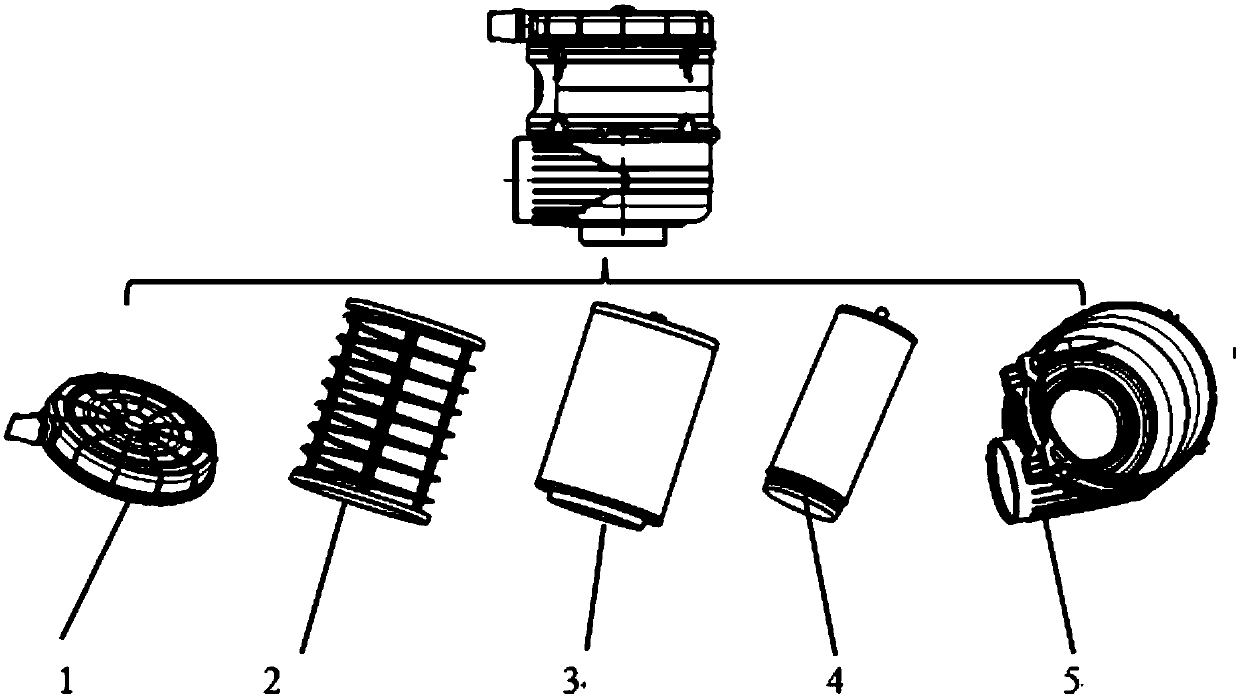
[0033] A spin-type air filter device, the structure of which is as follows figure 1 As shown, it includes upper end cover assembly 1, swirl plate 2, main filter element assembly 3, safety filter element assembly 4, and lower end cover assembly 5.

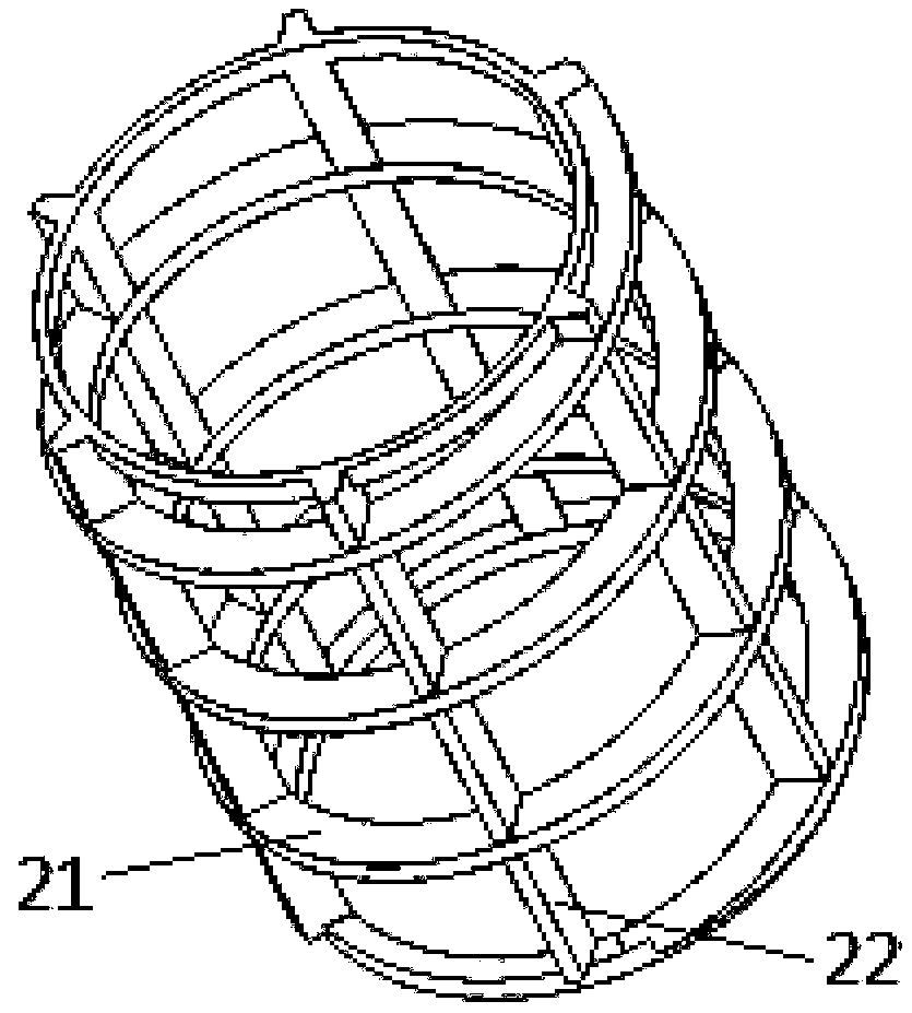
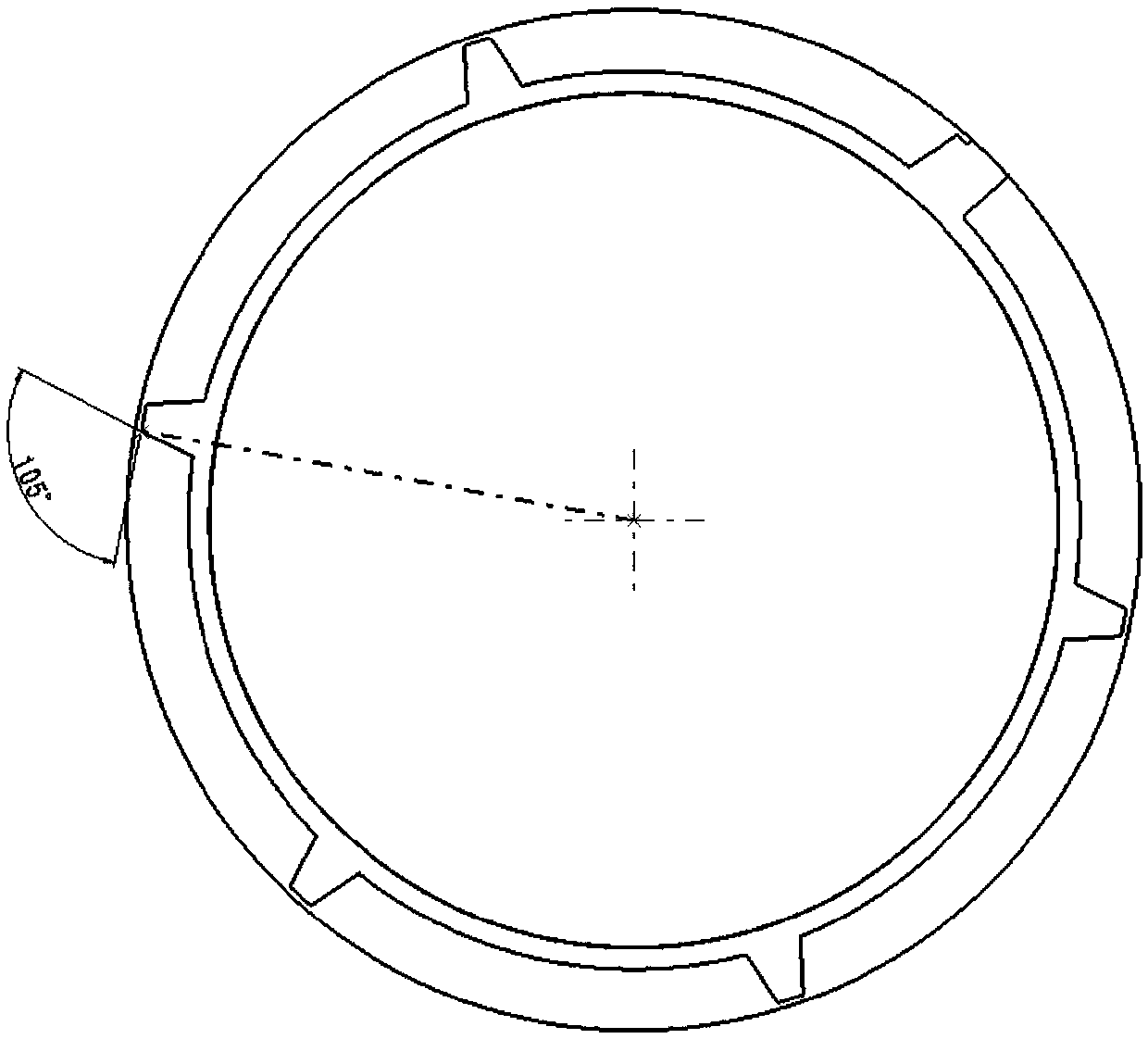
[0034] figure 2 , image 3 and Figure 4 Both are schematic diagrams of the structure of the swirl sheet, the swirl sheet 2 is integrally injected, and can be detachably mounted on the outside of the main filter element assembly 3 for easy reuse. The swirl vane 2 includes a spiral blade structure 21 and a baffle 22, wherein the baffle 22 is a cylindrical distribution frame structure; The external fixed connection; the rotation angle of the helical blade structure is 15°; the included angle between the baffle and the air intake is 105°; the helical blade structure 21 extends from one end of the baffle 22 to the other end.

[0035] Figure 5 It is a structural schematic diagram of the upper end cover assembly, the upper end cove...

Embodiment 2

[0042] A spin-type air filter device, the structure of which is as follows figure 1 As shown, it includes upper end cover assembly 1, swirl plate 2, main filter element assembly 3, safety filter element assembly 4, and lower end cover assembly 5.

[0043] The structure of the upper end cover assembly 1, the main filter element assembly 3, the safety filter element assembly 4, and the lower end cover assembly 5 of the spin-type air filter device is the same as that in embodiment 1, the difference is that in embodiment 2 The structural parameters of the swirl vanes are different from those of the swirl vanes in Example 1.

[0044] In Embodiment 2, the swirl plate is integrally injection-molded, and can be detachably mounted on the outside of the main filter element assembly, which is convenient for repeated use. The swirl vane includes a spiral blade structure and a baffle, wherein the baffle is a cylindrical distribution frame structure; the spiral blade structure is arranged ...

Embodiment 3

[0046] A spin-type air filter device, the structure of which is as follows figure 1 As shown, it includes upper end cover assembly 1, swirl plate 2, main filter element assembly 3, safety filter element assembly 4, and lower end cover assembly 5.

[0047] The structure of the upper end cover assembly 1, the main filter element assembly 3, the safety filter element assembly 4, and the lower end cover assembly 5 of the spin-type air filter device is the same as that in embodiment 1, the difference is that in embodiment 3 The structural parameters of the swirl vanes are different from those of the swirl vanes in Example 1.

[0048] In Embodiment 3, the swirl sheet is integrally injection-molded, and can be detachably mounted on the outside of the main filter element assembly, which is convenient for repeated use. The swirl vane includes a spiral blade structure and a baffle, wherein the baffle is a cylindrical distribution frame structure; the spiral blade structure is arranged ...


PUM


Abstract

The invention relates to a spin-type air filter device. The spin-type air filter device comprises an upper end cover assembly, a spinning disk, a main filter element assembly, a safety filter elementassembly and a lower end cover assembly; the upper end cover assembly is connected with the lower end cover assembly through a buckle to form a shell body, and an air inlet and an air outlet are formed in the lower end cover assembly; the main filter element assembly is installed in the shell body, an upper end cover of the main filter element assembly is installed in a rotating ring groove in theupper end cover assembly, and a lower end cover of the main filter element assembly is installed in a rotating ring groove in the lower end cover assembly; a filter element upper end cover of the safety filter element assembly is installed in a rotating ring groove of the upper part of the main filter element assembly, and the lower end of the safety filter element assembly is fixedly connected with the air outlet; and the spinning disk is detachably installed on the outer part of the main filter element assembly in a sleeving mode. Compared with the prior art, the spinning disk is added, thus the main filter element assembly can rotate by self under the drive of the air in the air inlet, the effects of dust discharge and ash removal are achieved through the centrifugal force of the mainfilter element assembly, and the advantages of long service life and convenient disassembly and assembly are achieved.

Description

technical field [0001] The present invention relates to a cleaning device for the air required by an internal combustion engine, and more particularly to a spin-on air cleaner device. Background technique [0002] At present, many air filter assemblies have the problem of reciprocating disassembly and assembly within the maintenance mileage, mainly to remove the dust adhering to the surface of the filter element, resulting in the need to stop the vehicle for manual cleaning at any time during operation; [0003] Another problem is that if the filter assembly does not contain a fixed swirl plate or an air inlet baffle, one part of the filter element of the filter assembly will be damaged by airflow impact for a long time, making the life of the entire filter element severely shortened; [0004] The current air filter assembly is fixed by the filter element, and the design of multiple dust removal during the manual maintenance cycle makes the whole maintenance process difficu...

Claims


Application Information

Patent Timeline
Patent Type & Authority Applications(China)
IPC IPC(8): F02M35/08F02M35/024F02M35/022
CPCF02M35/0223F02M35/02416F02M35/08
Inventor 王海亮
Owner MANNHUMMEL FILTER SHANGHAI
Why Eureka
Try Eureka