Power-on reset signal generator and related electronic device

A signal generator and electrical reset technology, applied in electronic switches, electrical components, pulse technology, etc., can solve problems such as the inability to define the initial state of storage elements, the inability to determine the behavior of electronic system circuits, etc., and achieve the effect of optimizing performance

Inactive Publication Date: 2020-03-10
ARTERY TECH CO LTD
View PDF3 Cites 1 Cited by
  • Summary
  • Abstract
  • Description
  • Claims
  • Application Information

AI Technical Summary

Problems solved by technology

During such transitions, if no reset command is provided, it is generally not possible to define the initial state of the storage element and thus the circuit behavior of the entire electronic system

Method used


Image

  • Power-on reset signal generator and related electronic device
  • Power-on reset signal generator and related electronic device
  • Power-on reset signal generator and related electronic device

Examples


Embodiment Construction

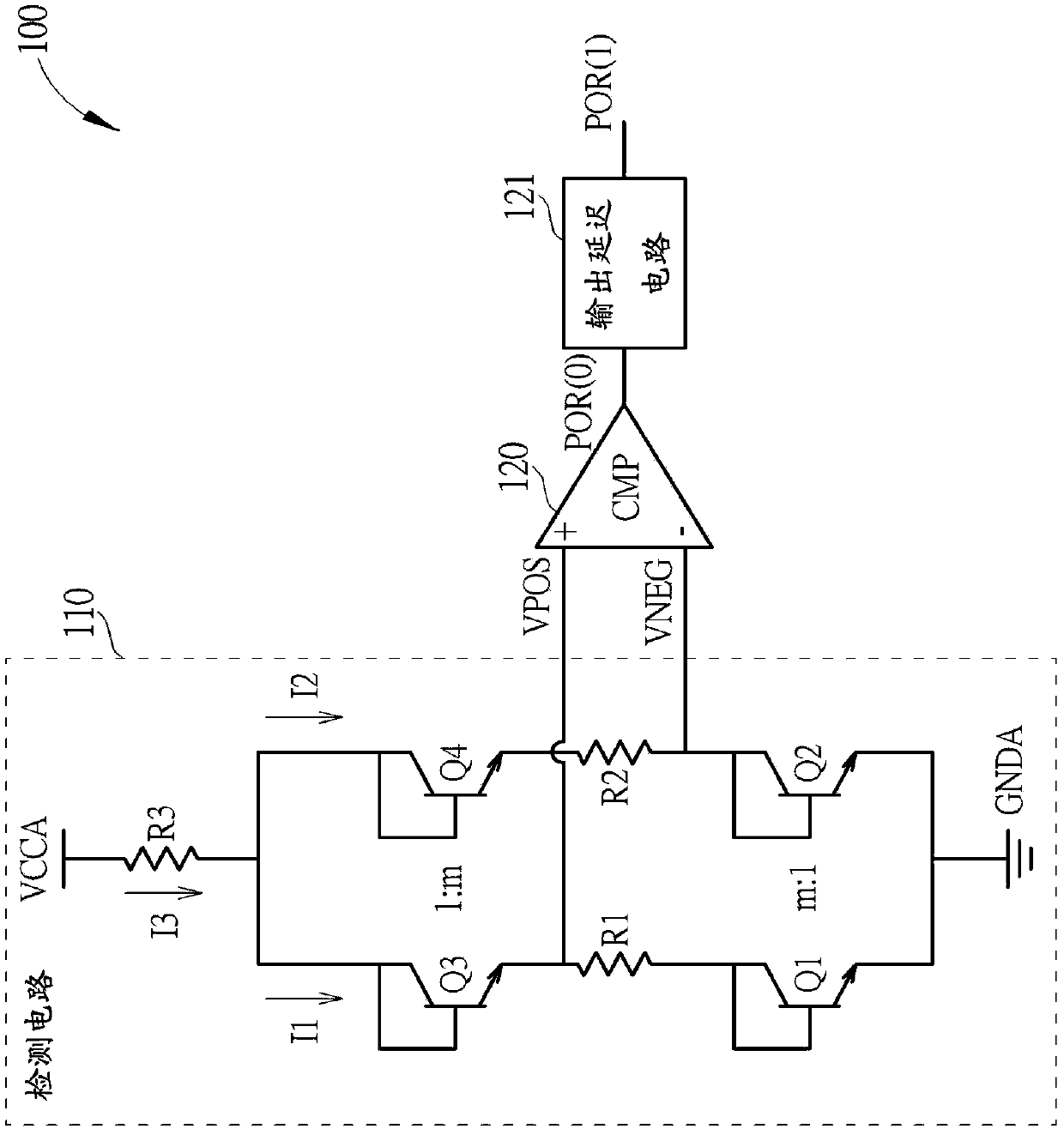
[0035] figure 1 It is a schematic diagram of a power-on reset signal generator 100 according to an embodiment of the present invention. The power-on reset signal generator 100 may include a detection circuit 110, a comparator (marked as "CMP") 120 and an output delay circuit 121, wherein the detection circuit 110 is coupled between a power supply voltage VCCA and a ground voltage GNDA , the comparator 120 is coupled to the detection circuit 110, and the output delay circuit 121 is coupled to the comparator 120, but the present invention is not limited thereto. In some embodiments, the output delay circuit 121 can be disposed outside the power-on reset signal generator 100 as a next-stage circuit.

[0036] According to this embodiment, the detection circuit 110 may include multiple sets of transistors stacked and coupled between the power supply voltage VCCA and the ground voltage GNDA, such as N sets of transistors (N is a positive integer greater than 1), and the multiple se...


PUM


Abstract

The invention discloses a power-on reset signal generator and a related electronic device. The power-on reset signal generator comprises a detection circuit and a comparator. The detection circuit detects a power supply voltage to generate a set of detection signals, and includes: a plurality of sets of transistors stacked and coupled between the power supply voltage and a ground voltage, each setof transistors including a first transistor and a second transistor respectively located in a first current path and a second current path; the first resistor and the second resistor are coupled between the two groups of transistors and are respectively positioned on the first current path and the second current path; and a third resistor coupled between the power supply voltage and the pluralityof groups of transistors. The comparator receives the set of detection signals from the detection circuit and compares the set of detection signals to generate a power-on reset signal. The power-on reset signal generator has the advantages that the power-on reset signal generator has high-precision control, and particularly, a voltage detection point VPOR required when a power-on reset signal isgenerated is irrelevant to temperature and a manufacturing process.

Description

technical field [0001] The present invention relates to power-on control, in particular to a power-on reset (POR) signal generator and related electronic devices. Background technique [0002] When powering up an electronic system, it takes a certain length of time for the power supply to stabilize the voltage and reach its steady state value. During such transitions, if no reset command is provided, it is generally not possible to define the initial state of the storage elements and thus the circuit behavior of the entire electronic system. According to the related art, a command signal for circuit initialization, such as a power-on reset signal, is generally required during or after power-on. The power-on-reset signal should keep the circuit in reset until the power supply reaches a steady-state voltage level, such as a level at which all circuits operate normally. [0003] There are still certain problems in such an architecture. For example, the voltage level of a cer...

Claims


Application Information

Patent Timeline
Patent Type & Authority Applications(China)
IPC IPC(8): H03K17/22
CPCH03K17/22H03K2017/226
Inventor 王维铁郝报田李超
Owner ARTERY TECH CO LTD
Why Eureka
Try Eureka