Eureka AIR delivers breakthrough ideas for toughest innovation challenges, trusted by R&D personnel around the world.

Filtering system

A filtration system and outlet channel technology, applied in the separation of dispersed particles, chemical instruments and methods, separation methods, etc., can solve problems such as poor configuration, inability to effectively utilize gas cyclone, poor filtration effect, etc., and reduce kinetic energy loss. , reduce power, good effect

Inactive Publication Date: 2020-03-13
孙正和 +1
View PDF0 Cites 0 Cited by
  • Summary
  • Abstract
  • Description
  • Claims
  • Application Information

AI Technical Summary

Problems solved by technology

However, it is known that the filtering device in the prior art is poorly configured so that the gas swirl cannot be effectively used, resulting in poor filtering effect

Method used


Image

  • Filtering system
  • Filtering system
  • Filtering system

Examples


Embodiment Construction

[0029] The following examples illustrate possible implementations of the present invention, but are not intended to limit the protection scope of the present invention.

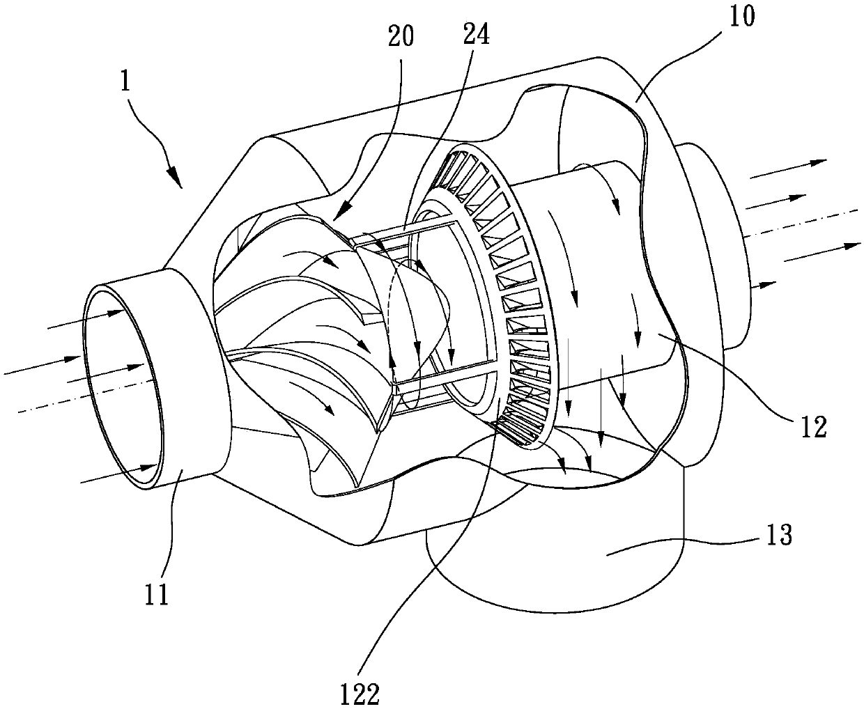
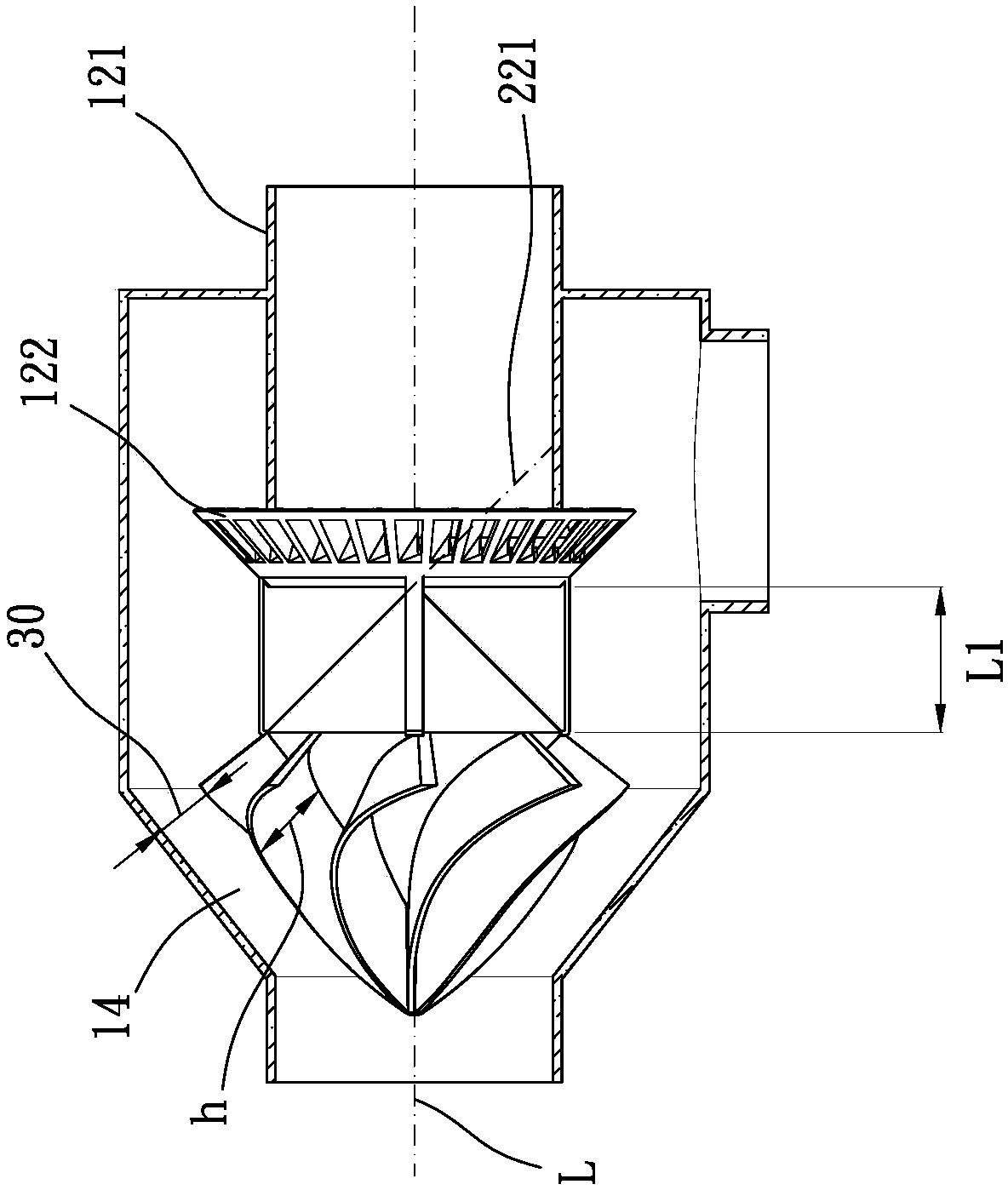
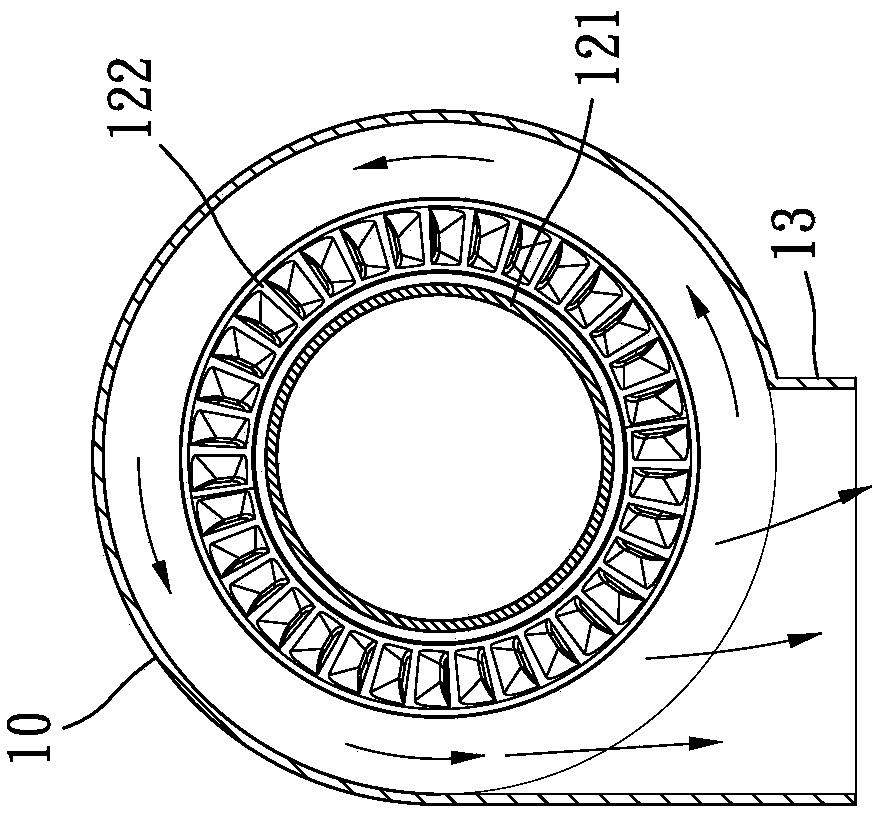
[0030] like Figure 1 to Figure 5 As shown, which shows a preferred embodiment of the present invention, the filter system 1 of the present invention includes a housing 10 and a flow guiding mechanism 20 .

[0031] The housing 10 includes an inlet channel 11 and an outlet channel 12 located on the same extension line L; The second tapered part 22 tapered in the direction of 12 and a plurality of blades 23, the plurality of blades 23 extend helically on the first tapered part 21 relative to the extension line L, the plurality of blades 23 and the housing 10 A gap 30 is formed between the inner walls of the vane 23 , and the gap 30 is smaller than a height h of the vane 23 relative to the surface of the first tapered portion 21 . The housing 10 , the inlet channel 11 , the outlet channel 12 , the first tapere...


PUM


Abstract

The invention provides a filtering system, which comprises: a shell, wherein the shell comprises an inlet channel and an outlet channel, and the inlet channel and the outlet channel are positioned onthe same extension line; and a flow guide mechanism, wherein the flow guide mechanism comprises a first gradually-reduced part gradually reduced towards the inlet channel, a second gradually-reduced part gradually reduced towards the outlet channel and a plurality of blades, the blades spirally extend to the first gradually-reduced part relative to the extension line, a gap is formed between the blade and the inner wall of the shell, and the height of the gap is smaller than the height of the blade relative to the surface of the first gradually-reduced part. According to the invention, the volume of the filtering system can be reduced, and the good filtering and separating effect is achieved; furthermore the three-dimensional cycloid is applied to the blade, and any cross sections, parallel to the surface of the first gradually-reduced part, of each blade are respectively located on a cycloid, so that after dust-containing gas enters from the inlet channel, the dust-containing gas moves on the blades along the path with the shortest residence time so as to reduce the kinetic energy loss caused by friction force; and the filtering system can achieve the excellent centrifugal separation effect and reduce the power required for feeding dust-containing gas into the filtering system by the power source.

Description

technical field [0001] The invention relates to the field of gas filtration, in particular to a filtration system. Background technique [0002] The general way to filter the dust-laden gas is to make the dust-laden gas cause a swirl, and use the principle of centrifugal force to separate the dust flowing outside the swirl from the dust-laden gas. Therefore, the device has a cylindrical housing forming a swirling flow space and a flow guide mechanism for swirling the dust-laden gas inside the housing. The structural design of the flow guiding mechanism and its cooperation with the housing directly affect the filtering effect of the dust gas. However, it is known that the filtering device in the prior art is poorly configured so that the gas swirl flow cannot be effectively utilized, resulting in poor filtering effect. [0003] Therefore, it is necessary to provide a novel and progressive filtering system to solve the above-mentioned problems. Contents of the invention ...

Claims


Application Information

Patent Timeline
Patent Type & Authority Applications(China)
IPC IPC(8): B01D45/16
CPCB01D45/16
Inventor 孙正和
Owner 孙正和
Why Eureka
Eureka Blog
Learn More