Forest fire extinguishing bomb rotorcraft device
A technology of rotorcraft and fire extinguishing bombs, applied in the direction of rotorcraft, launching devices, motor vehicles, etc., can solve the problems of low accuracy of fire extinguishing agent delivery, difficulty in accurately hitting the fire extinguishing point, difficulty in obtaining fire extinguishing effect, etc., and achieve short fire extinguishing preparation time , reduce casualties, simple structure
- Summary
- Abstract
- Description
- Claims
- Application Information
AI Technical Summary
Problems solved by technology
Method used
Image
Examples
Embodiment 1
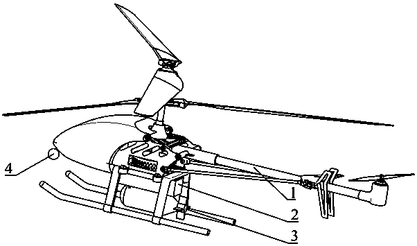
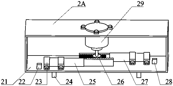
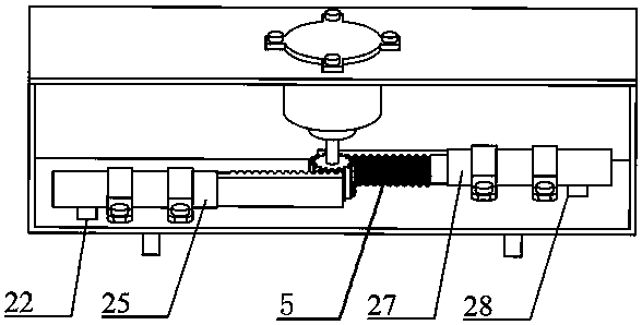
[0027] refer to Figure 1-7 , a rotorcraft device for forest fire extinguishing bombs, including a rotorcraft 1, the rotorcraft 1 is a coaxial double-blade rotor drone or a single-blade drone, including a fuselage, blades, power system, control system and image transmission system , can carry out vertical take-off and landing, and can be controlled manually or autonomously. The bottom of the rotorcraft 1 is fixedly installed with a release assembly 2 and a photoelectric pod 4, and the release assembly 2 is clamped with a fixed card. 2 includes a lower base plate 21, a front slot 22, four legs 24, a front bar 25, a gear 26, a rear bar 27, a rear slot 28, a drive assembly 29 and an upper base plate 2A, and the lower base plate 21 and the upper base plate 2A are close to each other Two symmetrically arranged side plates are fixedly installed on one side, the front slot 22 and the rear slot 28 are both arranged on the lower base plate 21, the drive assembly 29 is fixedly installed...
Embodiment 2
[0029]Further improved on the basis of Embodiment 1: the drive assembly 29 includes a drive box 2901 fixedly installed on the upper base plate 2A, a drive rod 2902 is rotatably connected to the top inner wall of the drive box 2901, and a drive rod 2902 is fixedly mounted on the bottom of the drive rod 2902. The disc 2906, the bottom of the rotating disc 2906 is fixedly equipped with a connecting shaft 2907, the bottom of the connecting shaft 2907 extends to the bottom of the drive box 2901 and is fixedly installed with the top of the gear 26, the outer side of the drive rod 2902 is covered with a worm gear 2903, and the drive box 2901 A stepper motor 2904 is fixedly installed on the inner wall of one side of the stepper motor 2904, and a worm 2905 is fixedly installed on the output shaft of the stepper motor 2904, and the worm 2905 and the worm wheel 2903 are meshed; the photoelectric pod 4 includes a camera and a cloud platform, and the platform is fixedly installed on the At ...
PUM
 Abstract
Description
Claims
Application Information
 - R&D
- Intellectual Property
- Life Sciences
- Materials
- Tech Scout
- Unparalleled Data Quality
- Higher Quality Content
- 60% Fewer Hallucinations
Browse by: Latest US Patents, China's latest patents, Technical Efficacy Thesaurus, Application Domain, Technology Topic, Popular Technical Reports.
© 2025 PatSnap. All rights reserved.Legal|Privacy policy|Modern Slavery Act Transparency Statement|Sitemap|About US| Contact US: help@patsnap.com


