Gas inlet gas-entraining passage structure with limit compartment length

A technology of intake port and intake passage, which is applied in the direction of fuel air intake port, combustion air/combustion-air treatment, fuel air filter, etc., can solve the problem of large gas pressure loss, low separation efficiency and low blocking efficiency and other problems, to achieve the effect of small intake pressure loss, increased cabin volume, and reduced layout space

Pending Publication Date: 2020-03-13
DONGFENG COMML VEHICLE CO LTD
View PDF0 Cites 1 Cited by
  • Summary
  • Abstract
  • Description
  • Claims
  • Application Information

AI Technical Summary

Problems solved by technology

The separation efficiency of gas and impurities is low, and in order to make the gas fully collide with the wall of the bleed air channel, the structural design inside the bleed air channel is very complicated, which is not conducive to practical application and economical manufacturing
At the same time, the intake grille of the bleed air duct is facing the splash, resulting in a low blocking efficiency (60.5%) of the grille for impurities, so the separation of moisture and other impurities contained in the gas passing through the intake grille is also through the airflow The separation efficiency is low (76.4%) by impacting the wall of the bleed air duct, and due to the complex internal design of the bleed air duct and many bends (up to 3 places), the pressure loss of the gas entering the bleed air duct is large (up to 3.55Kpa)
The reliability of the bleed airway structure is poor, which affects the service life of the entire air intake system, and the air filter needs to be replaced frequently, which increases the cost of later use

Method used


Image

  • Gas inlet gas-entraining passage structure with limit compartment length
  • Gas inlet gas-entraining passage structure with limit compartment length
  • Gas inlet gas-entraining passage structure with limit compartment length

Examples


Embodiment Construction

[0020] The present invention will be further described in detail below in conjunction with the accompanying drawings and specific embodiments.

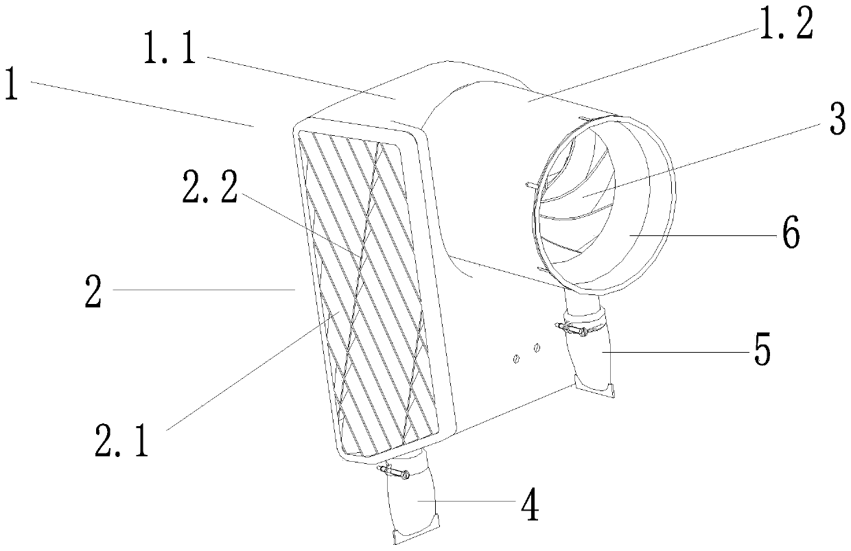
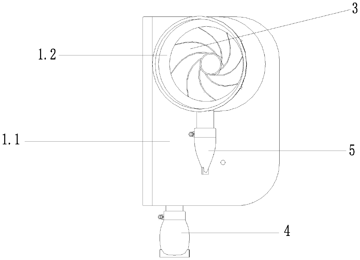
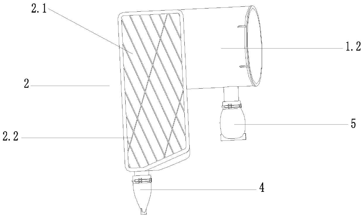
[0021] Such as figure 1 The intake bleed airway structure of the limit compartment length shown in -6 includes the bleed airway shell 1 and the intake grille 2, the bleed airway shell 1 includes the grille shell 1.1 and is perpendicular to the grille shell 1.1 The air inlet housing 1.2 is fixedly connected, and the surface of one side of the grille housing 1.1 is fixed with an air inlet grille 2, and the air inlet housing 1.2 is provided with a swirl fan 3 for separating gas and impurities, and the grille housing The body 1.1 is a square shell with a hollow inside, and the air inlet shell 1.2 is a cylindrical shell with a hollow inside. The intake channel from grid 2 to swirl fan 3.

[0022] The air intake grille 2 includes a plurality of grille vanes 2.1 arranged at intervals and parallel to each other, the angle between the grille...


PUM


Abstract

The invention discloses a gas inlet gas-entraining passage structure with a limit compartment length. The structure includes a gas-entraining passage shell and a gas inlet grill, the gas-entraining passage shell includes a grill shell and a gas inlet passage shell fixedly connected to the grill shell, the gas inlet grille is fixed on the surface of one side of the grille shell, a swirl flow separation device for separating gas and impurities is arranged in the gas inlet shell, and the gas inlet grill communicates with the swirl flow separation device through an inner cavity of the grille shelland an inner cavity of the gas inlet shell. The dust-removal and water-removal functions of the gas inlet gas-entraining passage structure with the limit compartment length designed by the inventionare completed by the swirl separation device in a gas-entraining passage, so that the arrangement space required for the gas-entraining passage is reduced, and the length of a compartment can be increased to increase the volume of the compartment; the reasonable design of a gas inlet grille angle increases the blocking efficiency of the gas inlet grille to impurities; the internal structure of thegas-entraining passage is simple, and the gas inlet pressure loss is small; and the overall structure has high efficiency of shunting and removing impurities.

Description

technical field [0001] The invention relates to the technical field of automobile air intake systems, in particular to a structure of an intake air intake channel with a limit compartment length. Background technique [0002] The bleed air channel structure adopted by the current limit compartment length is designed on the basis of the principle of separating gas and impurities by the impact of the air flow and the bleed air channel wall. The separation efficiency of gas and impurities is low, and in order to make the gas fully collide with the wall of the bleed air channel, the structural design inside the bleed air channel is very complicated, which is not conducive to practical application and economical manufacturing. At the same time, the intake grille of the bleed air duct is facing the splash, resulting in a low blocking efficiency (60.5%) of the grille for impurities, so the separation of moisture and other impurities contained in the gas passing through the intake g...

Claims


Application Information

Patent Timeline
Patent Type & Authority Applications(China)
IPC IPC(8): F02M35/024F02M35/08F02M35/10
CPCF02M35/024F02M35/02416F02M35/08F02M35/10Y02T10/12
Inventor 李岖蒋志刚
Owner DONGFENG COMML VEHICLE CO LTD
Why Eureka
Try Eureka