
Optimization method for silicon wafer alignment mark layout

A technology of alignment marks and optimization methods, which is applied in the manufacturing of electrical components, circuits, semiconductor/solid-state devices, etc. Yield, effect of reducing measurement time

Active Publication Date: 2020-03-13
INST OF MICROELECTRONICS CHINESE ACAD OF SCI
View PDF12 Cites 0 Cited by
  • Summary
  • Abstract
  • Description
  • Claims
  • Application Information

AI Technical Summary

Problems solved by technology

[0003] In order to solve the problem of low fitting accuracy of the alignment grid correction model due to silicon wafer deformation, the present invention proposes a silicon wafer alignment mark layout optimization method to realize the distribution of alignment marks on the silicon wafer surface and the individual alignment marks Reasonable optimization of numbers

Method used


Image

  • Optimization method for silicon wafer alignment mark layout
  • Optimization method for silicon wafer alignment mark layout

Examples


Embodiment Construction

[0015] In order to make the object, technical solution and advantages of the present invention clearer, the present invention will be further described in detail below in conjunction with specific embodiments and with reference to the accompanying drawings.

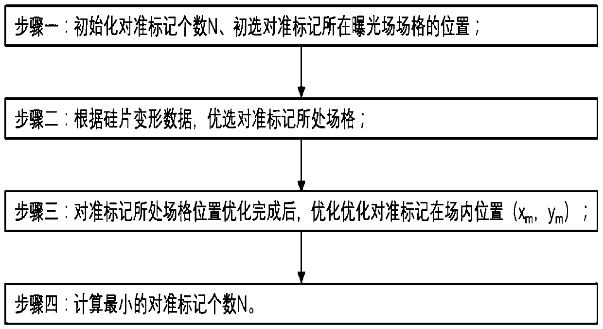
[0016] The invention discloses a method for optimizing the layout of a silicon wafer alignment mark, comprising:

[0017] Initialize the number of alignment marks, and select the field where the alignment marks are located;

[0018] According to the silicon wafer deformation data, optimize the field grid where the alignment mark is located;

[0019] Optimize the position of alignment marks in the grid;

[0020] Calculating the minimum number of alignment marks is to complete the silicon wafer alignment mark layout optimization.

[0021] In some embodiments of the present invention, the method for optimizing the field grid where the alignment mark is located includes performing least square fitting according to the measu...


PUM


Abstract

An optimization method for silicon wafer alignment mark layout comprises the steps of initializing the number of alignment marks and selecting field grids where the alignment marks are located; optimizing field grids where the alignment marks are located according to the silicon wafer deformation data; optimizing the positions of the alignment marks in the field grids; and calculating the minimumnumber of the alignment marks to finish the layout optimization of the alignment marks of the silicon wafer. According to the invention, the optimal alignment mark position is provided through the optimization method, so that the overlay alignment performance is improved; the minimum measurement number of the alignment marks is given through an optimization method, so that the measurement time ofan alignment system is shortened, and the possibility is provided for improving the yield.

Description

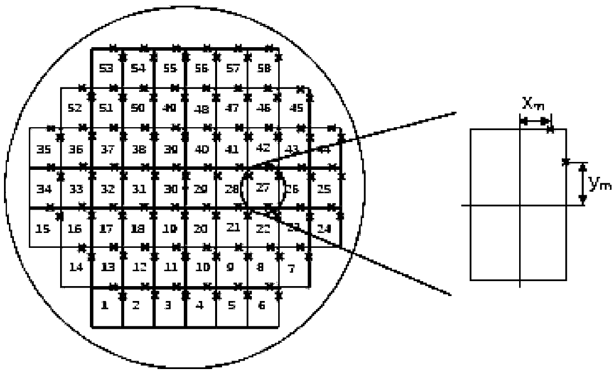
technical field [0001] The invention belongs to the technical field of integrated circuits or other precision manufacturing, in particular to a method for optimizing the layout of silicon chip alignment marks. Background technique [0002] In the field of integrated circuit manufacturing, through lithography equipment, the mask pattern is copied to the silicon wafer in a certain proportion. Mask wafer alignment is one of the most critical steps in the photolithography process. Usually the alignment mark is exposed together with the circuit pattern on the mask, and is located in the scribed groove on the edge of the field grid, such as the upper right corner of the field grid (such as figure 2 shown). By measuring the position of the alignment mark on the silicon wafer before the next layer of graphics is exposed, the position of the graphics to be exposed on the silicon wafer is calculated to achieve precise alignment between the two layers of graphics. Since it takes lon...

Claims


Application Information

Patent Timeline
Patent Type & Authority Applications(China)
IPC IPC(8): H01L21/68H01L21/67
CPCH01L21/682H01L21/67253
Inventor 李璟丁敏侠张清洋朱世懂折昌美谢冬冬武志鹏胡丹怡
Owner INST OF MICROELECTRONICS CHINESE ACAD OF SCI
Learn More