
Ceramic 3D printing device for performing drying through infrared lamp

An infrared lamp and printing device technology, applied in the field of 3D printing, can solve the problems of incapable ceramic parts reinforcement, local structural moisture content change, ceramic structure collapse, etc. Effect

Inactive Publication Date: 2020-03-17
HUNAN UNIV +1
View PDF3 Cites 0 Cited by
  • Summary
  • Abstract
  • Description
  • Claims
  • Application Information

AI Technical Summary

Problems solved by technology

Due to the fluidity of the ceramic paste with a high moisture content, if the structure of the printed ceramic parts is too high, under the influence of gravity, the underlying ceramic structure is prone to collapse, which will affect the overall printing effect
Existing ceramic 3D printers cannot strengthen the newly printed ceramic parts, and a few can only use additional equipment to process points or parts, which will cause a large change in the water content of the local structure and uneven shrinkage, resulting in printed ceramic parts. to crack

Method used


Image

  • Ceramic 3D printing device for performing drying through infrared lamp
  • Ceramic 3D printing device for performing drying through infrared lamp
  • Ceramic 3D printing device for performing drying through infrared lamp

Examples


Embodiment Construction

[0030] It should be noted that, in the case of no conflict, the embodiments of the present invention and the features in the embodiments can be combined with each other. The present invention will be described in detail below in conjunction with examples.

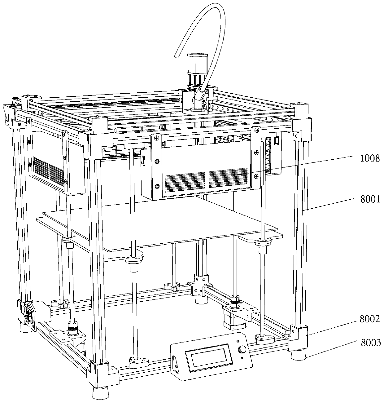
[0031] The present invention relates to a ceramic 3D printing device that utilizes infrared lamps to dry. The preferred embodiments of the present invention will be further described in detail below. For the convenience of description, in this technical solution, the definition figure 1 The end where the operating device is located is the front and the lower end, the power supply system is on the side, and the position where the ceramic printing device is located is the upper end, and it is stipulated that the beam where the operating device is located is along the X-axis direction, and the height direction of the 3D printing device is the Z-axis direction. The direction perpendicular to the Z axis is the Y axis direction....


PUM


Abstract

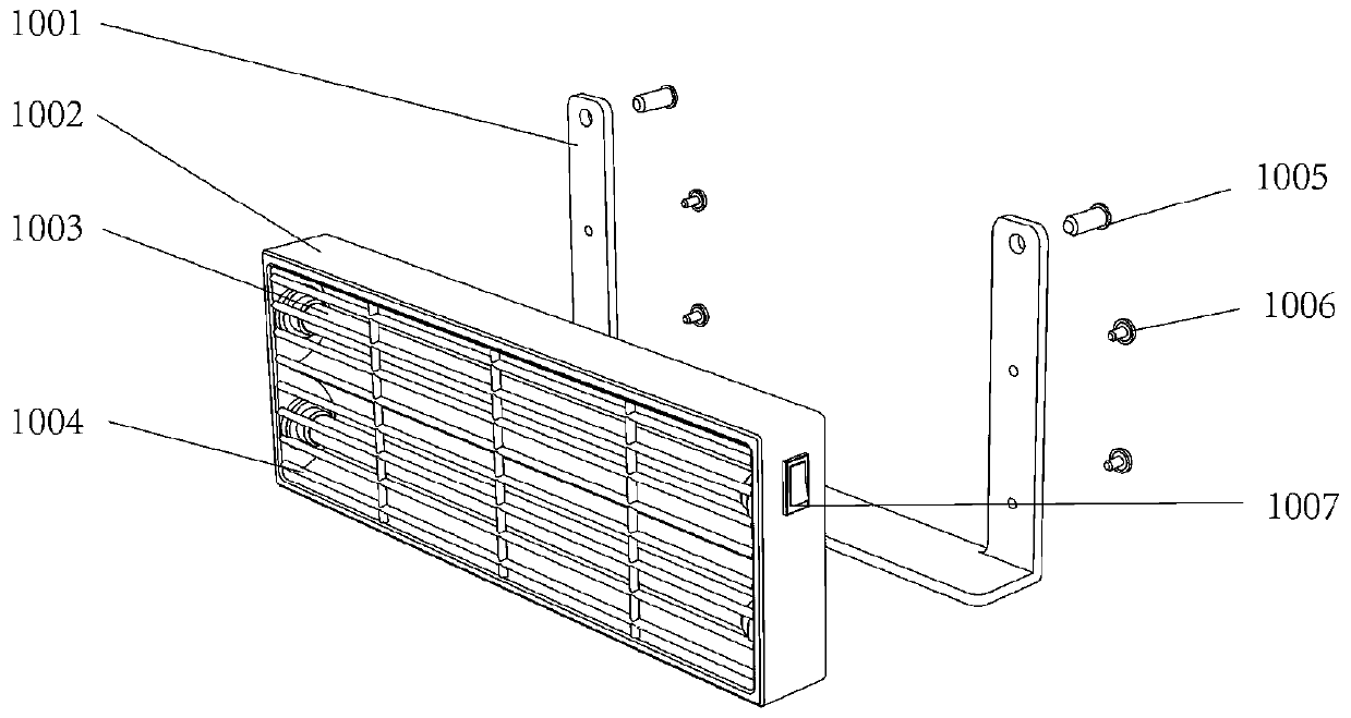
The invention discloses a ceramic 3D printing device for performing drying through an infrared lamp. The ceramic 3D printing device comprises a main frame, a printing platform arranged in the main frame, a ceramic printing device arranged on the upper part of the main frame, and the infrared lamp arranged on the main frame, wherein the printing platform can lift along the Z axis in the main frame,and the ceramic printing device can move along the X axis and the Y axis on the upper part of the main frame; and the ceramic printing device comprises a printing needle head, and the infrared lamp is fixed on the main frame corresponding to the height of the printing needle head. The structure is reasonable, the extrusion forming quality of ceramic paste in the ceramic 3D printing can be improved by slowly and uniformly reducing the moisture in the ceramic 3D printing paste, the part just printed can be effectively dried, and a technical foundation is provided for a ceramic 3D printer with larger printing volume, more complex structure and more variable styles.

Description

technical field [0001] The invention relates to the technical field of 3D printing, in particular to a 3D printing device for accelerated molding. Background technique [0002] Ceramic 3D printing technology is to extrude a ceramic paste with a high moisture content and superimpose it into ceramic parts. Since the ceramic paste with a high moisture content has certain fluidity, if the structure of the printed ceramic part is too high, under the influence of gravity, the underlying ceramic structure is prone to collapse, affecting the overall printing effect. Existing ceramic 3D printers cannot reinforce the newly printed ceramic parts, and a few can only use additional equipment to process points or parts, which causes a large change in the water content of the local structure and uneven shrinkage, resulting in printed ceramic parts. cracking. Contents of the invention [0003] In order to fill the gap in the prior art, the present invention provides a 3D printing device...

Claims


Application Information

Patent Timeline
Patent Type & Authority Applications(China)
IPC IPC(8): B28B1/00B33Y30/00
CPCB28B1/001B33Y30/00
Inventor 刘永红宋一鸣严妍殷彦琳
Owner HUNAN UNIV
Learn More