Connecting structure of unmanned aerial vehicle power controller

A connection structure and controller technology, applied in the field of unmanned aerial vehicles, can solve the problems of weak installation, screw wear, screw corrosion, etc., and achieve the effect of avoiding weak installation and simple structure

Inactive Publication Date: 2020-03-17
SUZHOU LVDIAN INFORMATION TECH CO LTD
View PDF1 Cites 0 Cited by
  • Summary
  • Abstract
  • Description
  • Claims
  • Application Information

AI Technical Summary

Problems solved by technology

[0003] The publication number is CN107963202A, which discloses a power controller system and operation method for a small long-endurance fixed-wing unmanned aerial vehicle, including a rectification and voltage stabilization module, which uses a three-phase rectifier bridge to convert the three-phase alternating current generated by the generator into an unmanned aerial vehicle. The DC power required by the electric control equipment, and the voltage is stabilized within a certain range. The interval power generation module includes the frequency-to-voltage module and the voltage-to-switch module. However, the common controllers are mostly connected to the UAV by screws. The HMI is used in a harsh environment, which can easily cause corrosion of the screws, and the controller needs to remove the screws during maintenance. The screws will wear out after frequent disassembly, resulting in unstable installation, and there is room for improvement.

Method used


Image

  • Connecting structure of unmanned aerial vehicle power controller
  • Connecting structure of unmanned aerial vehicle power controller
  • Connecting structure of unmanned aerial vehicle power controller

Examples


Embodiment Construction

[0020] The following will clearly and completely describe the technical solutions in the embodiments of the present invention with reference to the accompanying drawings in the embodiments of the present invention. Obviously, the described embodiments are only some, not all, embodiments of the present invention.

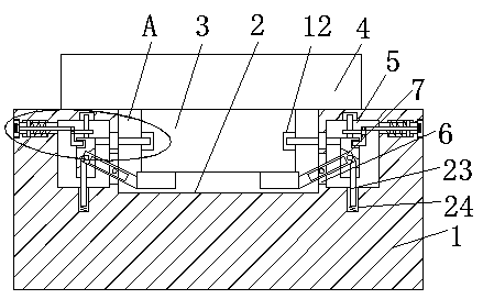
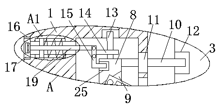
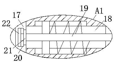
[0021] refer to Figure 1-3 , a connection structure of a UAV power controller, comprising a UAV 1, an installation groove 2 is provided on the top side of the UAV 1, an installation block 3 is movably installed in the installation groove 2, and the top side of the installation block 3 is fixed A controller 4 located above the UAV 1 is installed, and both sides of the installation groove 2 are provided with cavities 5 on the UAV 1, and the inner walls of the two cavities 5 close to each other are provided with swings. Hole 6, swing rod 7 is installed on the side inner wall of swing hole 6, and the two ends of swing rod 7 all extend to the outside of swing hole 6, and...


PUM


Abstract

The invention discloses a connecting structure of an unmanned aerial vehicle power supply controller. The structure comprises an unmanned aerial vehicle, a mounting groove is formed in the top side ofthe unmanned aerial vehicle; a mounting block is movably mounted in the mounting groove; a controller positioned above the unmanned aerial vehicle is fixedly mounted on the top side of the mounting block; cavities formed in the unmanned aerial vehicle are formed in the two sides of the mounting groove; swing holes are formed in the inner walls of the sides, close to each other, of the two cavities, swing rods are rotationally installed on the inner walls of one sides of the swing holes, the two ends of each swing rod extend out of the corresponding swing hole, rotating shafts are rotationallyinstalled on the inner walls of the top sides of the cavities, and rotating columns are fixedly installed at the bottom ends of the rotating shafts. The connecting structure is simple in structure, acommon bolt connection mode is changed, the problem that the controller cannot be dismounted due to corrosion or is not firmly mounted due to abrasion in the long-term use process of bolts is solved,the controller is more convenient and faster to maintain when needing to be maintained, and the requirements of people are met.

Description

technical field [0001] The invention relates to the technical field of unmanned aerial vehicles, in particular to a connection structure of an unmanned aerial vehicle power controller. Background technique [0002] Unmanned aircraft, referred to as "unmanned aerial vehicle", or "UAV" in English, is an unmanned aircraft that is controlled by radio remote control equipment and its own program control device, or is completely or intermittently operated autonomously by an on-board computer. [0003] The publication number is CN107963202A, which discloses a power controller system and operation method for a small long-endurance fixed-wing unmanned aerial vehicle, including a rectification and voltage stabilization module, which uses a three-phase rectifier bridge to convert the three-phase alternating current generated by the generator into an unmanned aerial vehicle. The DC power required by the electric control equipment, and the voltage is stabilized within a certain range. Th...

Claims


Application Information

Patent Timeline
IPC IPC(8): B64C39/02B64D47/00
CPCB64C39/02B64D47/00
Inventor 张宇周冰烨
Owner SUZHOU LVDIAN INFORMATION TECH CO LTD
Why Eureka
Try Eureka