
Traction gear box and rail vehicle

A technology of gearbox and gearbox body, applied in the field of rail vehicle transmission system, can solve the problems of low lubrication efficiency, increased power consumption, affecting the quality and service life of the gearbox, etc.

Inactive Publication Date: 2020-03-17
CRRC QINGDAO SIFANG CO LTD
View PDF6 Cites 4 Cited by
  • Summary
  • Abstract
  • Description
  • Claims
  • Application Information

AI Technical Summary

Problems solved by technology

Among the gears and bearings participating in the transmission, the gearbox needs to send relative sliding or movement during operation, so friction and wear will occur, which will increase power consumption and reduce transmission efficiency; especially for high-speed transmission, it is even more necessary to consider the lubrication of the gearbox
The quality of its lubrication system will affect the thermal balance of the entire gearbox and the wear of gears and bearings; in severe cases, it will also cause overheating or burning of gear segment teeth and bearings, which will seriously affect the quality and service life of the gearbox
[0003] At present, the lubrication of gearboxes is mostly achieved through forced and splash lubrication, and forced lubrication requires a characteristic installation space and a thin oil station; for some gearboxes with compact structures and limited installation dimensions, it can only be achieved through the principle of splash lubrication. accomplish
Traditional splash lubrication mainly depends on the size of the oil throwing ring to determine the lubrication of the gearbox. It is difficult to achieve the required lubrication effect in gearboxes with compact structure, limited installation size and gearboxes with high lubrication requirements, resulting in lubrication efficiency. low

Method used


Image

  • Traction gear box and rail vehicle
  • Traction gear box and rail vehicle
  • Traction gear box and rail vehicle

Examples


Embodiment Construction

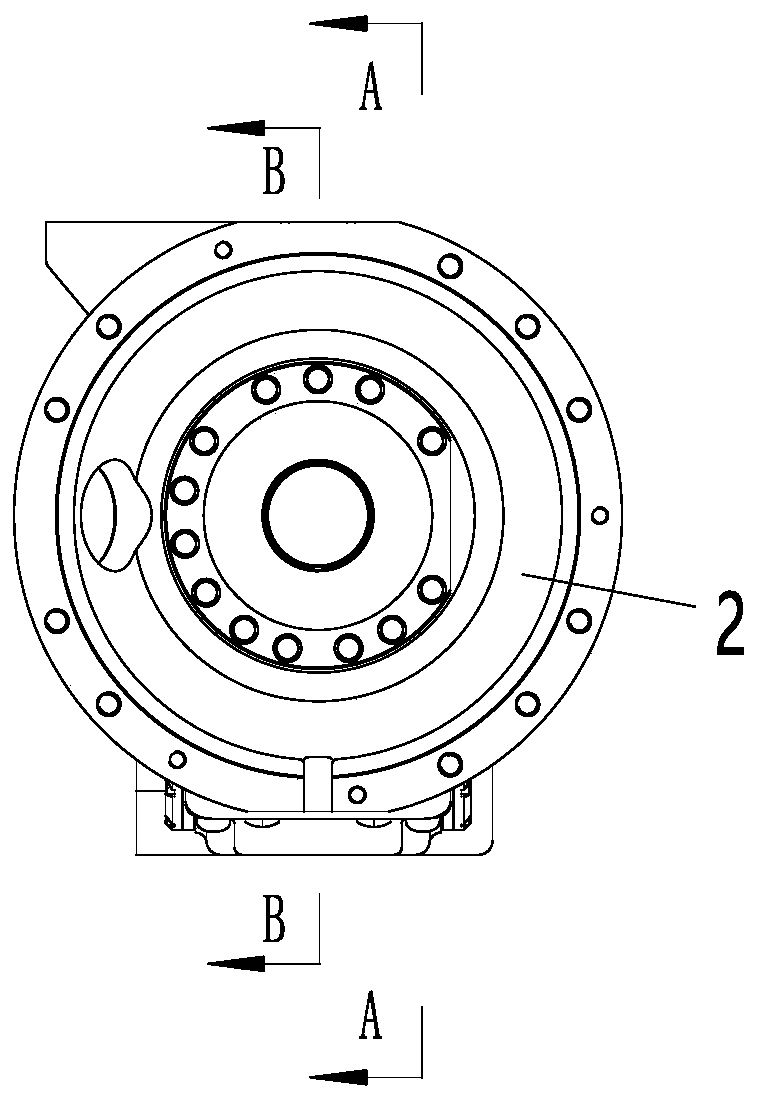
[0030] The specific implementation manners of the present invention will be further described in detail below in conjunction with the accompanying drawings and embodiments. The following examples are used to illustrate the present invention, but are not intended to limit the scope of the present invention.

[0031] In describing the present invention, it should be understood that the terms "center", "longitudinal", "transverse", "length", "width", "thickness", "upper", "lower", "front", " Back", "Left", "Right", "Vertical", "Horizontal", "Top", "Bottom", "Inner", "Outer", "Clockwise", "Counterclockwise", "Axial", The orientation or positional relationship indicated by "radial", "circumferential", etc. is based on the orientation or positional relationship shown in the drawings, and is only for the convenience of describing the present invention and simplifying the description, rather than indicating or implying the referred device or element Must be in a particular orientatio...


PUM


Abstract

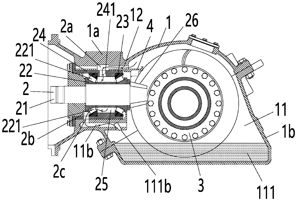
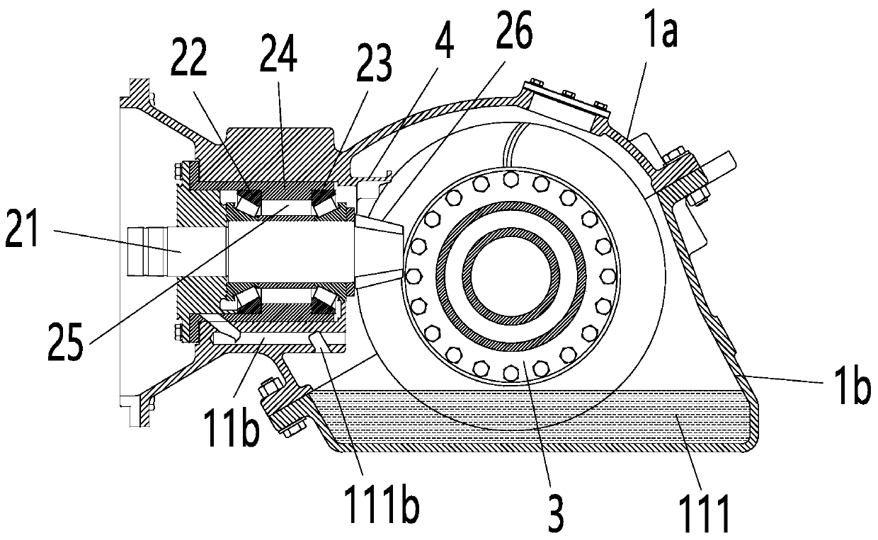
The invention relates to the technical field of a rail vehicle transmission system, and discloses a traction gear box and a rail vehicle. The traction gear box comprises a gear box body, a driving gear assembly, a driven gear assembly and an oil accumulation tank, wherein an accommodation cavity is constructed inside the gear box body; the driving gear assembly is arranged in the accommodation cavity; the driven gear assembly is meshed with the driving gear assembly; an oil pool for containing lubricating oil is constructed at a position in the accommodation cavity, which corresponds to the lower part of the driven gear assembly; the lower end of the driven gear assembly is infiltrated in the lubricating oil in the oil pool; the oil accumulation tank is formed on the inner wall of the gearbox body and positioned above the driving gear assembly; the oil accumulation tank is used for bearing the lubricating oil shaken by rotation of the driven gear assembly; an oil inlet passage is constructed inside the driving gear assembly; and the oil inlet passage is communicated with the oil accumulation tank through an oil inlet hole formed on the gear box body. The traction gear box has theadvantages of high lubricating efficiency and good lubricating effect.

Description

technical field [0001] The invention relates to the technical field of rail vehicle transmission systems, in particular to a traction gearbox and a rail vehicle. Background technique [0002] The lubrication system of the gearbox has the functions of lubrication, cooling, cleaning, rust prevention, sealing and hydraulic pressure. Among the gears and bearings involved in the transmission, the gearbox needs to send relative sliding or movement during operation, so friction and wear will occur, which will increase power consumption and reduce transmission efficiency; especially for high-speed transmission, it is even more necessary to consider the lubrication of the gearbox. The quality of its lubrication system will affect the thermal balance of the entire gearbox and the wear of gears and bearings; in severe cases, it will also cause overheating or burning of gear segment teeth and bearings, which will seriously affect the quality and service life of the gearbox. [0003] At...

Claims


Application Information

Patent Timeline
IPC IPC(8): F16H57/04
CPCF16H57/0424F16H57/0457
Inventor 侯建文张会杰张月军
Owner CRRC QINGDAO SIFANG CO LTD
Learn More