Valve body support and assembling method

An assembly method and valve body technology, which is applied in the direction of machines/brackets, supporting machines, mechanical equipment, etc., can solve problems such as cracks at the joint between pipes and valve bodies, fire or explosion, pipeline oil leakage, etc., to achieve assembly The effect of short time, reducing safety hazards and low cost

Inactive Publication Date: 2020-03-17
PETROCHINA CO LTD
View PDF8 Cites 1 Cited by
  • Summary
  • Abstract
  • Description
  • Claims
  • Application Information

AI Technical Summary

Problems solved by technology

[0004] Long-term pressure will cause the valve body to sink, and cracks or even breaks will appear at the connection between the pipe and the valve body, which will lead to oil leakage in the pipe, which is prone to dangerous situations such as fire or explosion, so there is a great safety hazard

Method used


Image

  • Valve body support and assembling method
  • Valve body support and assembling method
  • Valve body support and assembling method

Examples


Embodiment Construction

[0061] In order to make the technical solutions and advantages of the present invention clearer, the embodiments of the present invention will be further described in detail below in conjunction with the accompanying drawings.

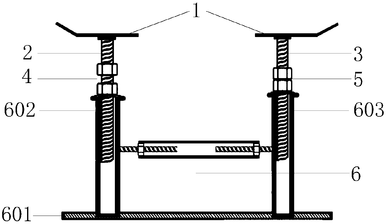
[0062] An embodiment of the present invention provides a valve body bracket, figure 1 It is a structural schematic diagram of a valve body bracket provided by an embodiment of the present invention, such as figure 1 As shown, the valve body bracket includes: a first support member 1, a first vertical screw rod 2, a second vertical screw rod 3, a first set of lock nuts 4, a second set of lock nuts 5 and a second support member 6 .

[0063] Wherein, the first end of the first vertical screw 2 and the first end of the second vertical screw 3 are respectively fixedly connected to the lower side of the first support member 1 . Optionally, the first end of the first vertical screw 2 and the first end of the second vertical screw 3 are respectively fixedly ...


PUM


Abstract

The invention relates to a valve body support and belongs to the technical field of oil exploitation. A first vertical screw rod and a second vertical screw rod in the valve body support are connectedwith a first support component. The vertical screw rod is sleeved with a first set of locking nuts, and the second vertical screw rod is sleeved with a second set of locking nuts. A second support component comprises a bottom guide groove, a first vertical support pipe, a second vertical support pipe and a width adjustment part. The first vertical support pipe and the second vertical support pipeare located in the bottom guide groove and movably connected with the bottom guide groove. The width adjustment part is connected with the first vertical support pipe and the second vertical supportpipe. The second end of the first vertical screw rod is inserted into the first vertical support pipe. The first set of locking nuts is used for locking the first vertical screw rod. The second end ofthe second vertical screw rod is inserted into the second vertical support pipe, and the second set of locking nuts is used for locking the second vertical screw rod. According to the valve body support, a valve body can be stably supported, the valve body is prevented from sinking or floating, and the safety is improved.

Description

technical field [0001] The invention relates to the technical field of oil exploitation, in particular to a valve body bracket and an assembly method. Background technique [0002] In the process of oil transportation, multiple pipelines are usually used, and the pipelines are connected by a valve body, which not only can connect the pipelines, but also can effectively control the flow of oil by adjusting the valve body. [0003] Since the valve body, pipeline and the oil being transported all have weight, this weight will cause pressure on the connection between the pipeline and the valve body. Moreover, when no oil is transported in the pipeline, gas needs to be delivered to the pipeline to achieve the effect of eliminating the air pressure in the pipeline, and the pressure relief process will also cause pressure at the connection between the pipeline and the valve body. [0004] Long-term pressure will cause the valve body to sink, and cracks or even breaks will appear a...

Claims


Application Information

Patent Timeline
Patent Type & Authority Applications(China)
IPC IPC(8): F16M11/04F16M11/26
CPCF16M11/041F16M11/26
Inventor 冯美河
Owner PETROCHINA CO LTD
Why Eureka
Try Eureka