Low-loss flexible circuit board

A flexible circuit board, low-loss technology, applied in the direction of circuit devices, printed circuit components, conductive pattern layout details, etc., can solve the problem that the radio frequency transmission performance is difficult to further improve, to reduce the equivalent dielectric constant and loss, reduce Effect of FPC thickness and performance improvement

Inactive Publication Date: 2020-03-17
MFLEX YANCHENG CO LTD
View PDF4 Cites 0 Cited by
  • Summary
  • Abstract
  • Description
  • Claims
  • Application Information

AI Technical Summary

Problems solved by technology

However, the current method of directly pressing FCCL boards (flexible copper foil substrate boards) made of PI / MPI / LCP substrates and copper foils into FPC transmission lines is limited by the inherent loss characteristics of substrates and copper foils. , its RF transmission performance is difficult to further improve, which brings great challenges to the design optimization of RF and antenna engineers

Method used


Image

  • Low-loss flexible circuit board
  • Low-loss flexible circuit board
  • Low-loss flexible circuit board

Examples


Embodiment 1

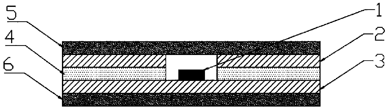
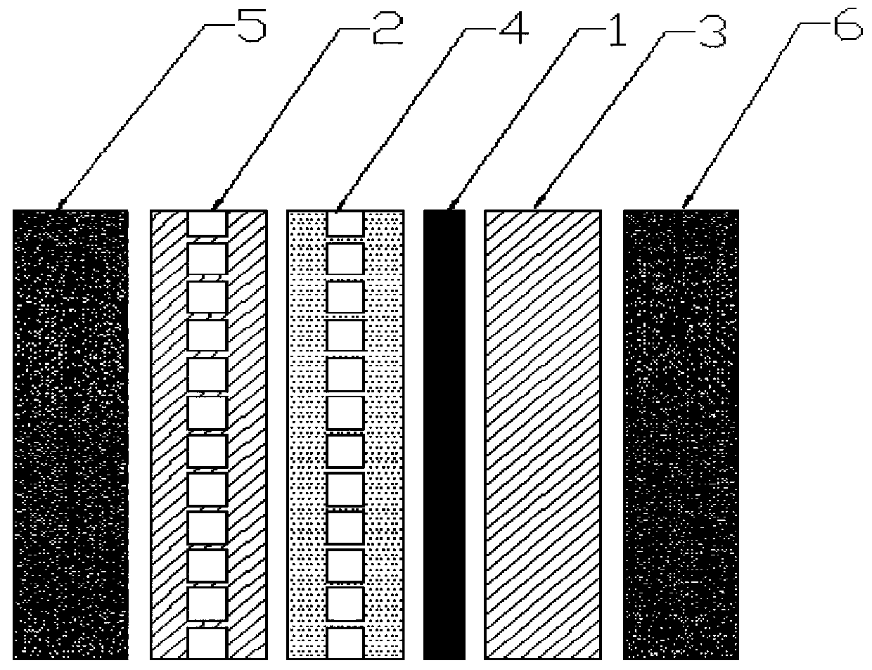
[0022] A low-loss flexible circuit board, comprising a signal line (1) and a first insulating layer (2) and a second insulating layer (3) respectively located on the upper side and the lower side of the signal line (1), the first insulating layer (2 ) and the second insulating layer (3) are connected through the first adhesive layer (4), the signal line (1) is in the same layer as the first adhesive layer (4), and the signal line (1) is pasted on the second insulating layer (3 ), the first insulating layer (2) and the first glue layer (4) are hollowed out in a grid pattern at the position of the signal line, and there is a first insulating layer (2) and the second insulating layer (3) outside A reference layer (5) and a second reference layer (6).

[0023] Specifically, the insulating layer is PI (polyimide) or MPI (heterogeneous PI) or LCP (liquid crystal polymer) material, and the reference layer is copper foil.

Embodiment 2

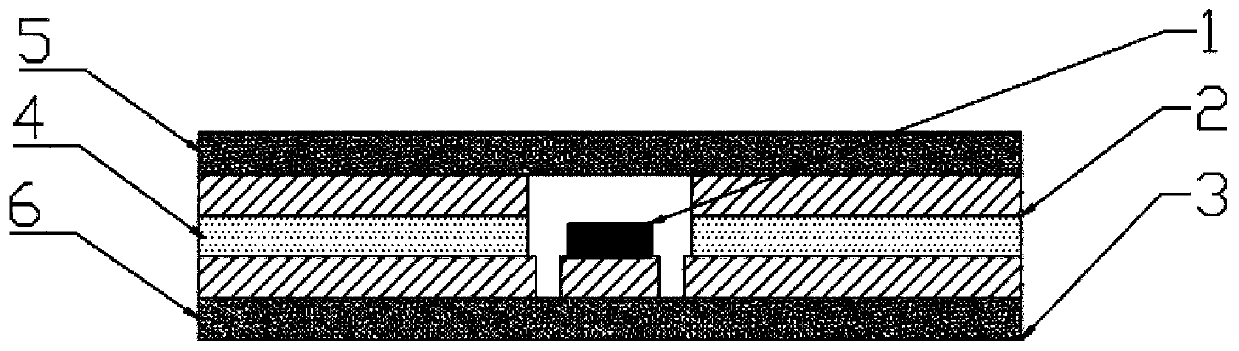
[0025] A low-loss flexible circuit board, comprising a signal line (1) and a first insulating layer (2) and a second insulating layer (3) respectively located on the upper side and the lower side of the signal line (1), the first insulating layer (2 ) and the second insulating layer (3) are connected through the first adhesive layer (4), the signal line (1) is in the same layer as the first adhesive layer (4), and the signal line (1) is pasted on the second insulating layer (3 ), the first insulating layer (2) and the first adhesive layer (4) are hollowed out in a grid pattern at the position of the signal line, and the part of the second insulating layer (3) that is not facing the signal line is hollowed out. There are also a first reference layer (5) and a second reference layer (6) outside the insulating layer (2) and the second insulating layer (3).

[0026] Specifically, the insulating layer is PI (polyimide) or MPI (heterogeneous PI) or LCP (liquid crystal polymer) mater...

Embodiment 3

[0028] A low-loss flexible circuit board, comprising a signal line (1) and a first insulating layer (2) and a second insulating layer (3) respectively located on the upper side and the lower side of the signal line (1), the first insulating layer (2 ) and the second insulating layer (3) are connected through the first adhesive layer (4), the signal line (1) is in the same layer as the first adhesive layer (4), and the signal line (1) is pasted on the second insulating layer (3 ), the first insulating layer (2) and the first adhesive layer (4) are hollowed out in a grid pattern at the position of the signal line, and there is a third insulating layer (7) on the lower side of the second insulating layer (3). The insulating layer (7) is connected to the second insulating layer (3) through the second adhesive layer (8), and there are also a first reference layer (5) and a second insulating layer (5) outside the first insulating layer (2) and the third insulating layer (7). Two ref...


PUM


Abstract

Along with the arrival of the 5G communication era. The application of a terminal MIMO (Multiple Input Multiple Output) antenna is gradually popularized; as an excellent integration platform, the FPC(flexible circuit board) can integrate a plurality of radio frequency signal transmission lines on one FPC at the same time, and compared with a traditional mode that a plurality of flexible coaxial cables need to be adopted to carry out signal feed-in on the MIMO antenna, the space is greatly saved. However, an existing FPC transmission line is limited by inherent loss characteristics of the basematerial and the copper foil, the radio frequency transmission performance of the existing FPC transmission line is difficult to further improve, and great challenges are brought to design optimization of radio frequency and antenna engineers. According to the invention, the latticed hollowing design is carried out on the insulating base material and the glue around the signal line, so that the equivalent dielectric constant and loss of the material through which the signal transmission line passes are reduced, the performance of the transmission line is improved, and the loss of the transmission line is reduced under the condition of the same FPC thickness, or the FPC thickness is reduced under the condition of the same loss.

Description

technical field [0001] The invention relates to the field of flexible circuit board manufacturing, in particular to a low-loss flexible circuit board. Background technique [0002] With the advent of the 5G communication era, the application of terminal MIMO (Multi-Input Multiple-Output technology) antennas is becoming more and more popular. As an excellent integration platform, FPC (Flexible Circuit Board) can integrate multiple radio frequency signal transmission lines on one FPC at the same time. Compared with traditional The need to use multiple flexible coaxial cables to feed the signal to the MIMO antenna greatly saves space. However, the current method of directly pressing FCCL boards (flexible copper foil substrate boards) made of PI / MPI / LCP substrates and copper foils into FPC transmission lines is limited by the inherent loss characteristics of substrates and copper foils. , its radio frequency transmission performance is difficult to further improve, which brings...

Claims


Application Information

Patent Timeline
Patent Type & Authority Applications(China)
IPC IPC(8): H05K1/02
CPCH05K1/0256H05K1/0296
Inventor 马磊李伟业万克宝唐晓峰李海江刘亚会沈晶
Owner MFLEX YANCHENG CO LTD
Why Eureka
Try Eureka