Garden planting soil improvement method

A soil improvement and gardening technology, which is applied in the direction of soil preparation, agricultural machinery and tools, heating, etc., can solve the problems of destroying the soil structure, inconvenient operation, and costing a lot of manpower and material resources, so as to improve the soil, facilitate construction and operation, and avoid waste of resources Effect

Inactive Publication Date: 2020-03-20
深圳市奥城景观工程设计有限公司
View PDF13 Cites 6 Cited by
  • Summary
  • Abstract
  • Description
  • Claims
  • Application Information

AI Technical Summary

Problems solved by technology

[0004] The above existing technical solutions have the following defects: when the soil is raked or loosened, a large amount of external force is required to destroy the soil structure, a large amount of manpower and material resources are required, and the operation is very inconvenient. Therefore, there is still room for improvement

Method used


Image

  • Garden planting soil improvement method
  • Garden planting soil improvement method
  • Garden planting soil improvement method

Examples


Embodiment 1

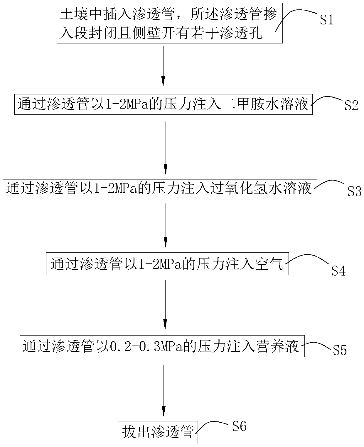
[0048] refer to figure 1 , is a garden planting soil improvement method disclosed by the present invention, comprising the following steps:

[0049] S1. Draw grid lines on the soil to be improved. The grid is square and the side length of the grid is 3m. Insert the permeation pipe vertically downward at the intersection of the grid. The insertion end of the permeation pipe is closed and conical. The outer diameter of the insertion end gradually decreases along the square away from the center point of the permeation tube. There are several densely distributed permeation holes on the side wall of the permeation tube. The diameter of the permeation hole is 0.1-0.2mm. The distance between the permeation hole farthest from the insertion end of the permeation tube and the insertion end of the permeation tube is 30 cm.

[0050] S2. After mixing dimethylamine and water evenly with a mass ratio of 1:0.5, inject the dimethylamine aqueous solution into the permeation pipe through a wate...

Embodiment 2

[0056] The difference with embodiment 1 is:

[0057] The side length of the grid in S1 is 4m;

[0058] The mass ratio of dimethylamine to water in S2 is 1:0.75, the water injection pressure is 1.5MPa, and the injection time of dimethylamine aqueous solution is 55s;

[0059] The mass ratio of hydrogen peroxide to water in S3 is 1:0.65, the water injection pressure is 1.5MPa, and the injection time of hydrogen peroxide aqueous solution is 60s;

[0060] The air injection pressure in S4 is 1.5MPa, and the air injection time is 7.5min;

[0061] The injection pressure of the nutrient solution in S5 is 0.25MPa.

Embodiment 3

[0063] The difference with embodiment 1 is:

[0064] The side length of the grid in S1 is 5m;

[0065] The mass ratio of dimethylamine to water in S2 is 1:1, the water injection pressure is 2MPa, and the injection time of dimethylamine aqueous solution is 60s;

[0066] The mass ratio of hydrogen peroxide to water in S3 is 1:0.9, the water injection pressure is 2MPa, and the injection time of hydrogen peroxide aqueous solution is 65s;

[0067] The air injection pressure in S4 is 2MPa, and the air injection time is 10min;

[0068] The injection pressure of the nutrient solution in S5 is 0.3MPa.


PUM


Abstract

The invention relates to the technical field of soil improvement, in particular to a garden planting soil improvement method which comprises the following steps: S1, a permeation tube is inserted intosoil, a doping section of the permeation tube is closed, and a plurality of permeation holes are formed in the side wall of the permeation tube; S2, a dimethylamine aqueous solution is injected at the pressure of 1-2 MPa through the permeation tube; S3, a hydrogen peroxide aqueous solution is injected at the pressure of 1-2 MPa through the permeation tube; S4, air is injected through the permeation tube at the pressure of 1-2 MPa; S5, a nutrient solution is injected through the permeation tube at the pressure of 0.2-0.3 MPa; S6, the permeation tube is pulled out. The method has the advantages that large-area excavation is not needed for harrowing or loosening soil, a large amount of manpower and material resources are not consumed, and construction operation is easy and convenient.

Description

technical field [0001] The invention relates to the technical field of soil improvement, in particular to a soil improvement method for garden planting. Background technique [0002] At present, after the soil has not been taken care of for a long time, there will be agglomeration, which will lead to a decrease in the air permeability of the soil, which will cause the roots of the plants planted in the soil to be hypoxic and suffocate, causing the roots to rot, which is harmful to the health of the plants. The soil is improved. [0003] Existing soil improvement methods mainly use physical means to rake or loosen the soil, so that the soil can return to a fluffy state again, thereby restoring air permeability. [0004] The above existing technical solutions have the following defects: when the soil is raked or plowed, a large amount of external force is required to destroy the soil structure, a large amount of manpower and material resources are required, and the operation ...

Claims


Application Information

Patent Timeline
Patent Type & Authority Applications(China)
IPC IPC(8): A01B79/00A01B79/02A61L2/06
CPCA01B79/00A01B79/02A61L2/06
Inventor 何勇涛
Owner 深圳市奥城景观工程设计有限公司
Why Eureka
Try Eureka