Anesthetic machine small in occupied space

A space-occupied, anesthesia machine technology, which is applied in the field of anesthesia machines, can solve the problems of poor practicability, high vertical height, and large space occupied by anesthesia machines, and achieve the effects of convenient overall cleaning, reduced occupied space, and saved occupied space

Inactive Publication Date: 2020-03-20
YANTAI YUHUANGDING HOSPITAL
View PDF8 Cites 0 Cited by
  • Summary
  • Abstract
  • Description
  • Claims
  • Application Information

AI Technical Summary

Problems solved by technology

[0003] However, the anesthesia machines currently used in the hospital environment take up a lot of space, and the upper and lower spaces of the operating platform in the middle are not fully utilized. At the same time, the upper and lower fixed structures also cause the vertical height to be too high, making it difficult to perform daily maintenance and dust-proof treatment. Sex is not strong

Method used


Image

  • Anesthetic machine small in occupied space
  • Anesthetic machine small in occupied space
  • Anesthetic machine small in occupied space

Examples


Embodiment 1

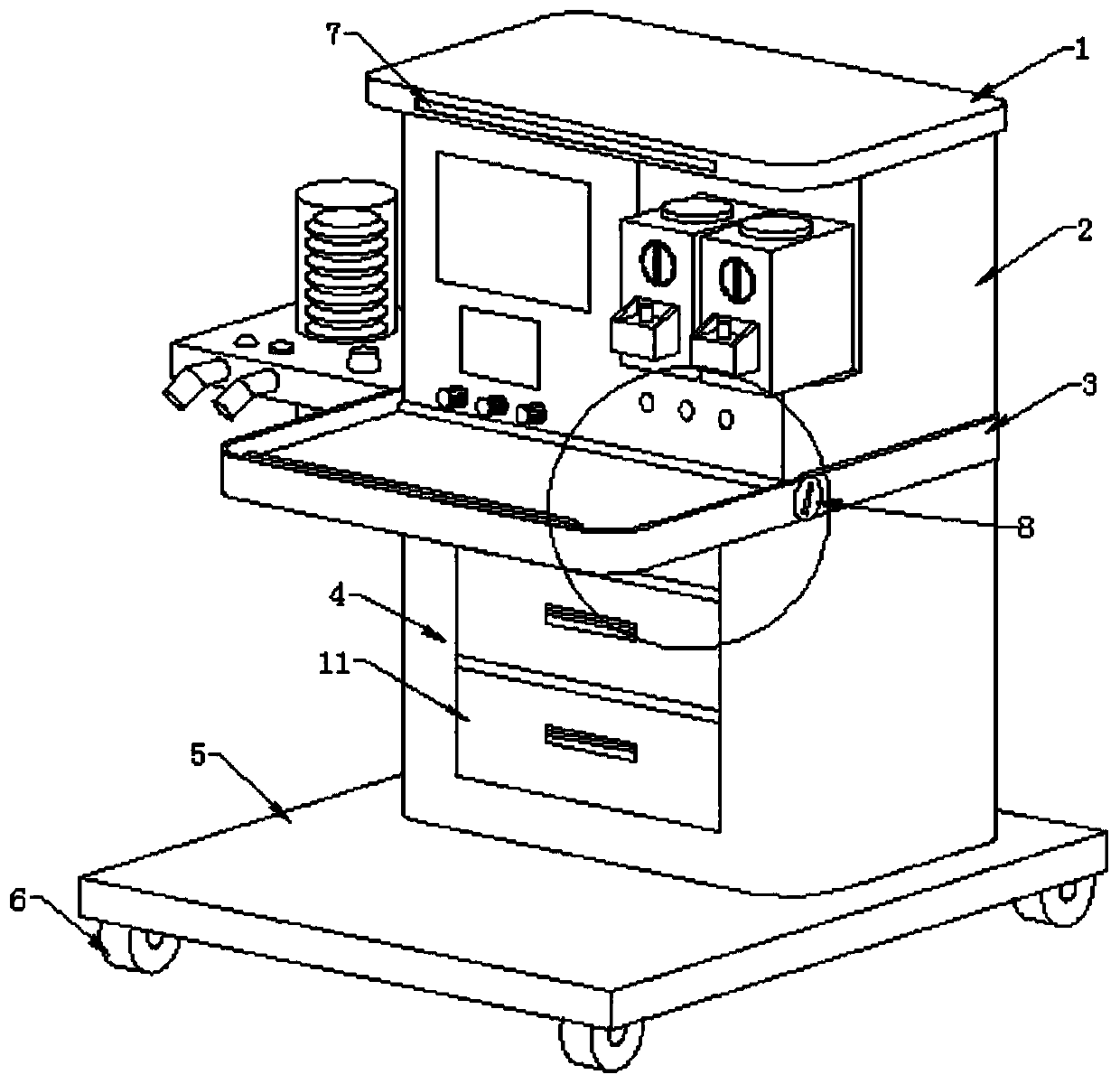
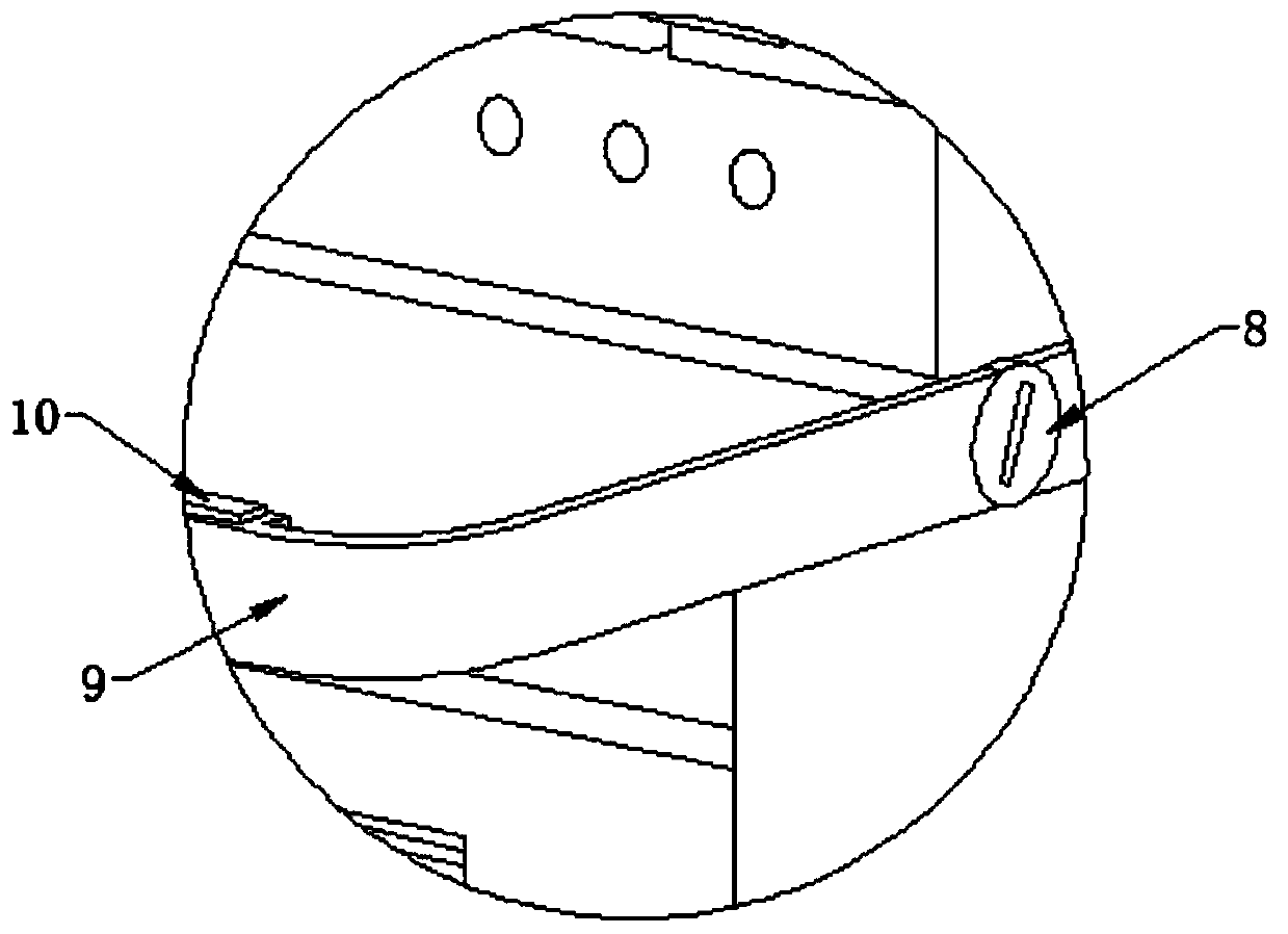
[0024] Such as Figure 1-2 As shown, the present invention provides a kind of anesthesia machine that occupies little space, comprises top cover 1, anesthesia box 2, fixed base 3, storage box 4 and placement platform 5, and the bottom end of top cover 1 is equipped with anesthesia box 2, anesthesia box The bottom end of 2 is equipped with fixed base 3, and the bottom end of fixed base 3 is equipped with storage box 4, and the bottom end of storage box 4 is equipped with placement platform 5, and the bottom end of placement platform 5 is equipped with universal wheel 6, and the universal wheel The wheel 6 is installed symmetrically in the center, a groove 7 is arranged on one side of the top cover 1, a rotating shaft 8 is installed on one end of the fixed base 3, an operating platform 9 is installed on one end of the rotating shaft 8, and an operating platform 9 is installed on the top of one side of the operating platform 9. There is a magnet block 10, and one end of the stora...

Embodiment 2

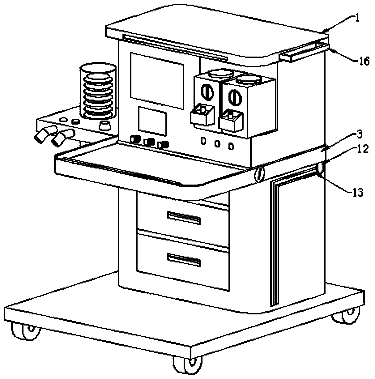
[0029] Such as Figure 3-4 As shown, the storage box 4 is fixedly connected to the placement platform 5, the storage box 4 and the drawer 11 are slidingly connected, the number of the drawers 11 is at least two, and the height of the storage box 4 is the same as that of the anesthesia box 2, so that the storage box 4 The drawer 11 on the surface is a plane handle structure, and its height can facilitate the operation of the anesthesia box 2 by medical personnel.

[0030] The bottom ends of both sides of the fixed base 6 are equipped with slide blocks 12, the two ends of the storage box 4 are equipped with right-angle slide rails 13, and the slide blocks 12 and the right-angle slide rails 13 are slidingly connected, between the storage box 4 and the fixed base 3 A slit 14 is provided, and the inside of the slit 14 is provided with a small roller, which is movably connected with the fixed base 3, a hinge hasp 15 is installed on the upper surface of the rear end of the storage bo...


PUM


Abstract

The invention discloses an anesthetic machine small in occupied space. The anesthetic machine small in occupied space comprises a top cover, an anaesthesia box, a fixed base, a storage box and a placing platform, wherein the anaesthesia box is mounted at the bottom end of the top cover; the fixed base is mounted at the bottom end of the anaesthesia box; the storage box is mounted at the bottom endof the fixed base; the placing platform is mounted at the bottom end of the storage box, and universal wheels are mounted at the bottom end of the placing platform, and are mounted in central symmetry; a groove is formed in one side of the surface of the top cover; a rotating shaft is mounted at one end of the fixed base, an operating platform is mounted at one end of the rotating shaft, and a magnet piece is mounted at the top end of one side of the operating platform; and drawers are mounted at one end of the storage box. According to the anesthetic machine disclosed by the invention, the rotating shaft is mounted at the middle of the operating platform, when the anesthetic machine does not need to be used, the operating platform can rotate along the rotating shaft to shelter equipmentof which the surface is exposed on the anesthetic machine, and the purpose of performing dustproof treatment on the equipment of which the surface is exposed under the situation of saving the occupiedspace can be achieved.

Description

technical field [0001] The invention relates to the field of medical equipment, in particular to an anesthesia machine with a small footprint. Background technique [0002] The anesthesia machine sends the anesthetic into the alveoli of the patient through a mechanical circuit, forming a partial pressure of the anesthetic gas, which diffuses into the blood, and directly inhibits the central nervous system, thereby producing the effect of general anesthesia. The anesthesia machine is a semi-open anesthesia device. It is mainly composed of anesthesia evaporation tank, flow meter, folding bellows ventilator, breathing circuit (including suction and expiration one-way valve and manual airbag), corrugated pipeline and other components. [0003] However, the anesthesia machines currently used in the hospital environment take up a lot of space, and the upper and lower spaces of the operating platform in the middle are not fully utilized. At the same time, the upper and lower fixed...

Claims


Application Information

Patent Timeline
Patent Type & Authority Applications(China)
IPC IPC(8): A61M16/01A61M16/00
CPCA61M16/01A61M16/0003
Inventor 崔峰鹤安仲哲
Owner YANTAI YUHUANGDING HOSPITAL
Why Eureka
Try Eureka