
Intelligent workpiece chuck device for manual chuck type numerical control lathe

A technology of CNC lathes and manual chucks, which is applied to chucks, accessories of toolholders, turning equipment, etc., can solve problems such as difficulty in grasping the torque of fixed workpieces, inability to achieve intelligence, and inability to directly apply electric cutterheads, etc. Achieve the effect of non-contact control, simple and compact structure, and reliable operation

Inactive Publication Date: 2020-03-20
青岛市技师学院
View PDF12 Cites 0 Cited by
  • Summary
  • Abstract
  • Description
  • Claims
  • Application Information

AI Technical Summary

Problems solved by technology

[0004] In order to overcome the inconvenience that existing lathes using manual chucks can only use manual chucks to fix workpieces, the existing electric cutter heads cannot be directly applied to the use of manual chuck lathes, and in the use of electric chucks to fix workpieces, the operation It is difficult for personnel to grasp the torque of the fixed workpiece and the disadvantages of being unable to achieve intelligence. The present invention provides a simple and compact structure, which can be directly installed on the manual chuck without any modification, and can also ensure the normal operation of the manual chuck. Use, the manual chuck can be used to fix the workpiece after a fault occurs, it has the advantages of both the electric chuck and the manual chuck, the work is more reliable, it is intelligent, it can realize non-contact control, and it can stop automatically after fixing the workpiece. On the premise of ensuring the effective fixing of the workpiece, it brings convenience to the operator and improves the work efficiency. The intelligent workpiece chuck device used by the manual chuck type CNC lathe

Method used


Image

  • Intelligent workpiece chuck device for manual chuck type numerical control lathe
  • Intelligent workpiece chuck device for manual chuck type numerical control lathe

Examples


Embodiment Construction

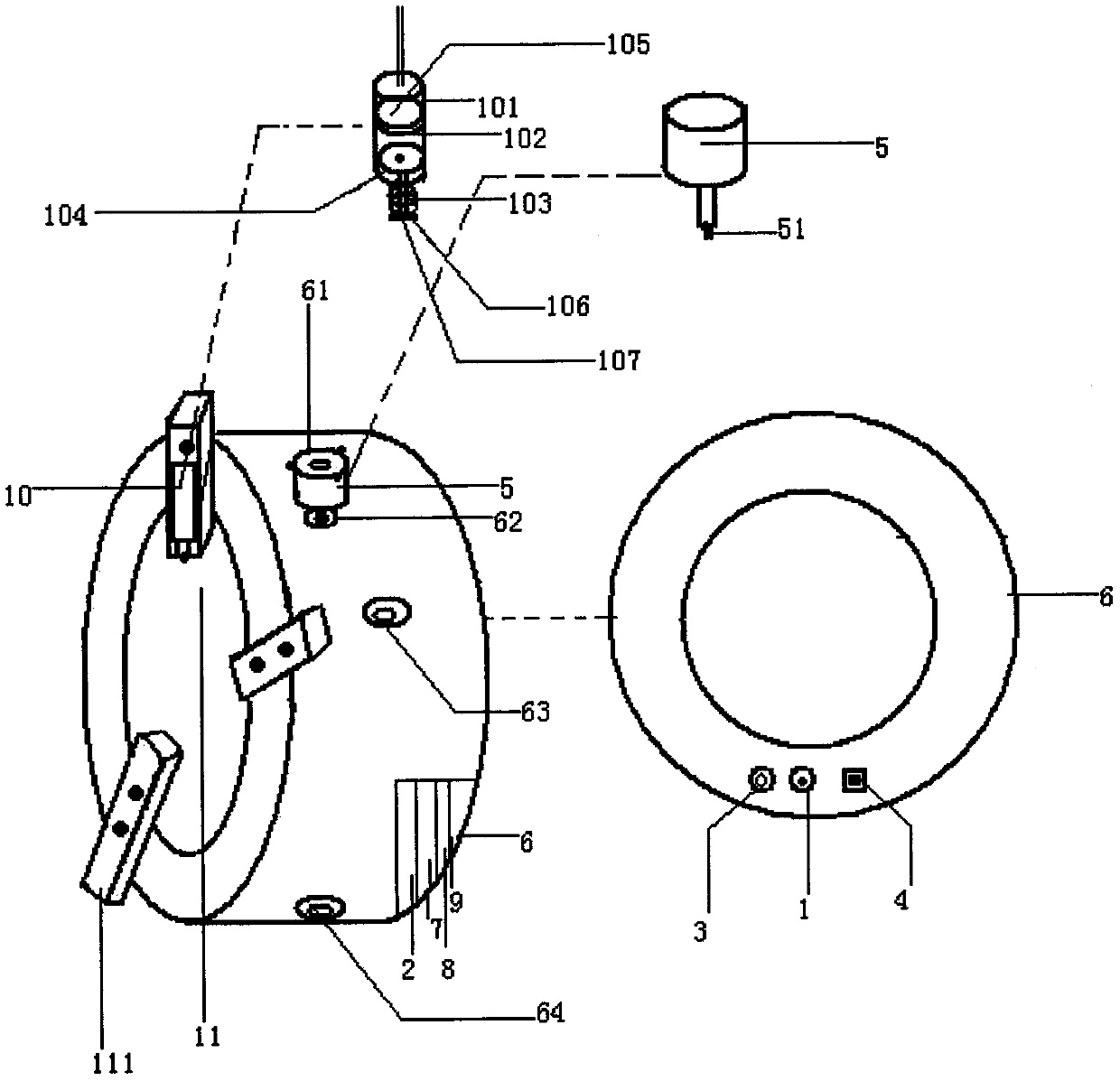
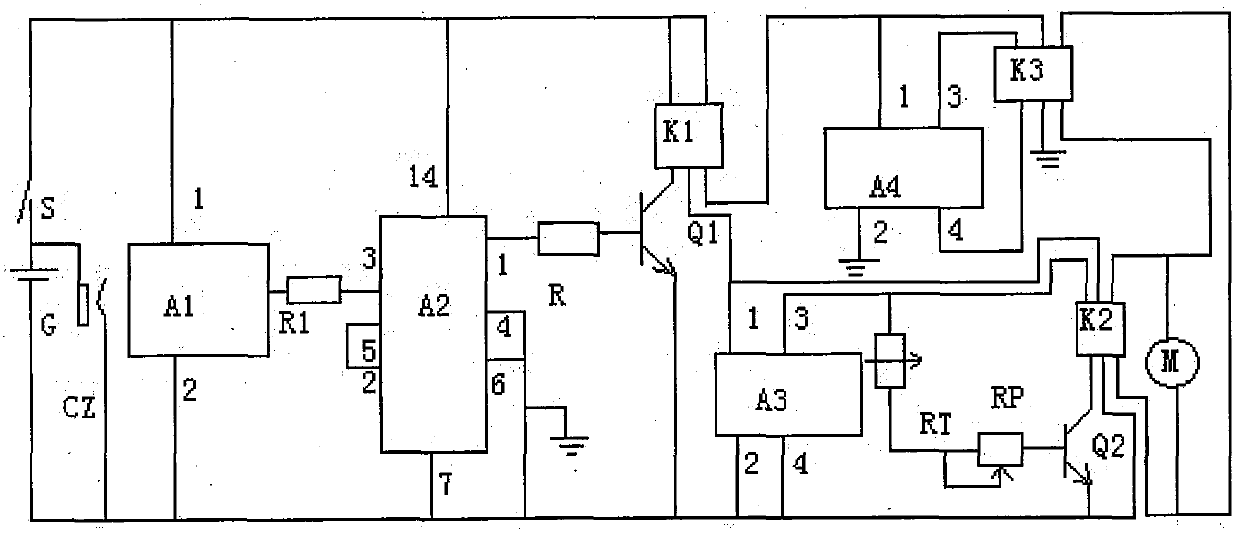
[0016] figure 1 As shown in , the intelligent workpiece chuck device used by the manual chuck type CNC lathe includes a photoelectric switch 1, a battery 2, a charging socket 3, a power switch 4, a motor deceleration mechanism 5, an annular metal casing 6, and a trigger circuit 7 , the first control circuit 8, the second control circuit 9, the trigger mechanism 10; the metal casing 6 has two layers inside and outside, a lower opening 62 is arranged in the middle of the inner layer of the metal casing 6, and the outer layer of the metal casing 6 There is an upper opening 61 in the middle, the upper opening 61 and the lower opening 62 are aligned, and the side end of the upper opening 61 has a plurality of fixing holes. A plurality of screw nuts are fixedly installed between the inner and outer layers of the metal casing 6 respectively; the inner diameter of the inner layer of the metal casing 6 is slightly larger than the outer diameter of the manual chuck 11, and the middle ou...


PUM


Abstract

The invention relates to an intelligent workpiece chuck device for a manual chuck type numerical control lathe. The device comprises a photoelectric switch, a storage battery, a charging socket, a power switch, a motor speed reducing mechanism, an annular sleeve shell, a trigger circuit, a first control circuit, a second control circuit and a trigger mechanism; the motor speed reducer is arrangedbetween the inner layer and the outer layer of the sleeve shell; a rectangular sleeve at the lower end of a power output shaft of the motor speed reducing mechanism is inserted into a rectangular sleeve hole at the upper end of a bevel gear of a manual chuck; a permanent magnet is arranged in the rear side of a cylinder body of the trigger mechanism, and the rear side of the cylinder body is perpendicularly attracted to the outer side of one clamping jaw of the manual chuck; the photoelectric switch, the storage battery, the charging socket, the power switch, the trigger circuit, the first control circuit and the second control circuit are installed in an element box and connected with the motor speed reducing mechanism through wires. The device can be directly installed on the manual chuck for use without modification, normal manual operation of the manual chuck can be guaranteed, convenience is brought to operators, and the working efficiency is improved.

Description

technical field [0001] The invention relates to the field of supporting equipment for a numerically controlled lathe, in particular to an intelligent workpiece chuck device for a manual chuck type numerically controlled lathe. Background technique [0002] CNC lathes are widely used machining equipment because of their high precision in processing workpieces, saving labor and improving work efficiency. An important part of CNC lathe is workpiece chuck equipment, which is a necessary facility for fixed installation of various workpieces. The most widely used CNC lathe is the manual three-jaw workpiece chuck. During operation, the operator needs to rotate the small bevel gear of the rotating workpiece chuck equipment such as a wrench left and right, and the small bevel gear drives the driven large bevel gear to rotate left and right. , and furthermore, the driven large bevel gear drives the jaws of the three-jaw chuck to close or open under the action of the relevant mechanis...

Claims


Application Information

Patent Timeline
Patent Type & Authority Applications(China)
IPC IPC(8): B23B31/169B23B31/28
CPCB23B31/16083B23B31/28
Inventor 高维珊
Owner 青岛市技师学院
Learn More