Closing device for a vehicle

A technology for equipment and vehicles, applied in vehicle components, leaf shutters, vehicle safety arrangements, etc., to solve problems such as driver inference, foreign objects not providing control, and inability to reliably identify trapped foreign objects.

Active Publication Date: 2020-03-20
CONTINENTAL AUTOMOTIVE TECH GMBH
View PDF5 Cites 0 Cited by
  • Summary
  • Abstract
  • Description
  • Claims
  • Application Information

AI Technical Summary

Problems solved by technology

However, a disadvantage of such systems is that from the reaction of the movement of the closing body to the drive, it cannot always be reliably detected whether a foreign object (also referred to as a trapped object) is actually trapped in the closing area.
This is also due to the fact that the force to be exerted during the movement of the closing body depends on several factors (e.g. mechanical play, temperature, wear, etc.), and therefore the reaction of the movement of the closing body to the drive cannot always be deduced unambiguously in the closing area Clamped objects in
[0008] This is particularly problematic when the closing of the closing body is performed without visual contact of the operator and thus no control is provided regarding the possible trapping of foreign objects in the closing area

Method used


Image

  • Closing device for a vehicle
  • Closing device for a vehicle
  • Closing device for a vehicle

Examples


example 1

[0066] Minimum spring rate TB negative Average spring rate TB positive Maximum spring rate SLS 20N / mm -42.86% 35 N / mm +42.86% 50 N / mm KUFE 16 N / mm -20% 20 N / mm +20% 24 N / mm GES 8.9 N / mm -29.19% 12.6 N / mm +29.19% 16.2 N / mm

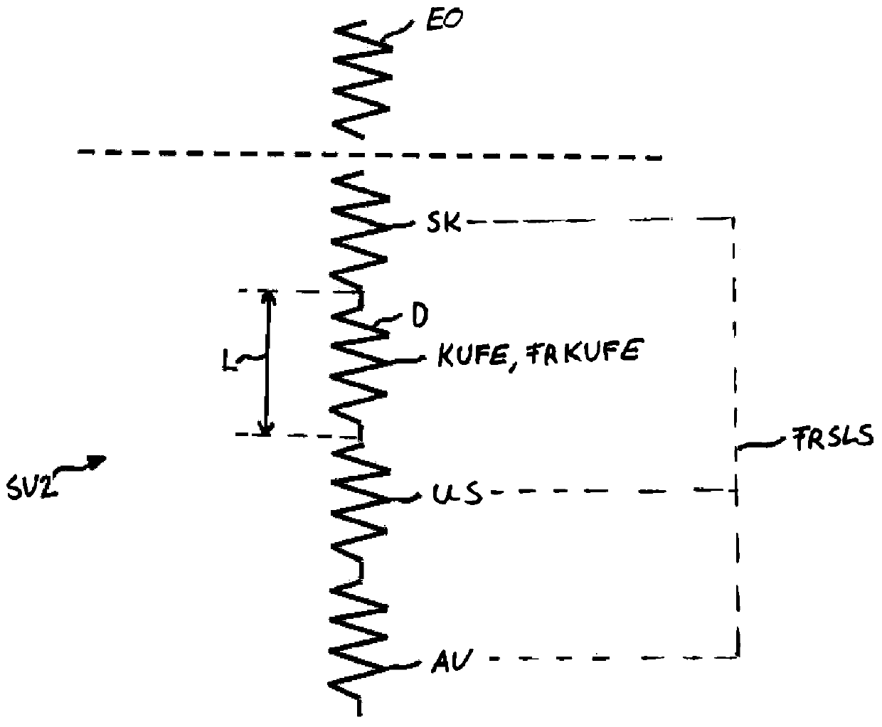
[0067] In Example 1, the closing system SLS has, for example, a closing system spring rate FRSLS of 35 N / mm, which has a closing system spring rate tolerance range TSLS of 42.86%. Consequently, the closing system spring stiffness (eg based on the above-mentioned effects) fluctuates between values ​​of 20 N / mm and 50 N / mm. Furthermore, a force transmission spring unit KUFE having a force transmission spring stiffness FRKUFE of 20 N / mm is arranged in the closing system SLS. When the force transmission spring stiffness FRKUFE has a force transmission spring stiffness tolerance range TKUFE of 20%, the force transmission spring stiffness FRKUFE (for example based on the aforementioned effects) fluctu...

example 2

[0070] Minimum spring rate TB negative Average spring rate TB positive Maximum spring rate SLS 20N / mm -42.86% 35 N / mm +42.86% 50 N / mm KUFE 7.5N / mm -25% 10 N / mm +25% 12.5 N / mm GES 5.5 N / mm -29.41% 7.7N / mm +29.41% 10.0 N / mm

[0071] In Example 2, the closing system SLS has the same closing system spring rate FRSLS of 35 N / mm, which has the same closing system spring rate tolerance range TSLS of 42.86%. In contrast to Example 1, however, a force transmission spring unit KUFE with a force transmission spring stiffness FRKUFE of 10 N / mm was selected. The force transmission spring stiffness tolerance range TKUFE can thus be increased up to 25% without the resulting overall spring stiffness FRGES having a total spring stiffness tolerance range TGES of more than 30%.

[0072] In example 2, a softer force transmission spring unit KUFE was selected than in example 1. At the same time, however, a larger force-transmitting sp...


PUM


Abstract

A closing device for opening and closing an opening in a vehicle is disclosed. The closing device comprises a closing system, having a closing body (SK) that is fitted on the vehicle (FZ) in a movablemanner and is configured to open and close the opening (O), a drive device (AV) that is operatively connected to the closing body (SK) and is configured to move the closing body (SK), and a transmission system (US) that is arranged between the closing body (SK) and the drive device (AV) and is configured to transmit a drive force generated by the drive device (AV) to the closing body (SK). The closing system (SLS) has a closing system spring rate (FRSLS) that characterizes an overall elasticity of the closing body (SLS), of the drive device (AV) and of the transmission system (US). The closing device (SV) also comprises a force transmission spring unit (KUFE) that is configured to pick up the drive force transmitted from the drive device (AV) to the closing body (SK). The force transmission spring unit (KUFE) has a force transmission spring rate (FRKUFE) that is lower than the closing system spring rate (FRSLS).

Description

technical field [0001] The invention relates to a closing device, in particular a power-operated closing device, for opening and closing an opening in a vehicle. Background technique [0002] In vehicle or motor vehicle construction, closing devices are also used as power-operated window lifters, power-operated sunroof drives, power-operated door or tailgate drives, or power-operated separating walls. The closing system moves the closing body for closing the opening in the vehicle. The drive of the closing body is realized, for example, by an electric motor which transmits a force acting on the closing body for opening and closing the opening by means of a corresponding transmission device, for example a guide formed in or on the opening. [0003] The area between the open position of the closing body, in which the greatest possible accessibility of the opening is provided, and the closed position of the closing body, in which the opening is completely or as far as possible...

Claims


Application Information

Patent Timeline
Patent Type & Authority Applications(China)
IPC IPC(8): E05F15/48
CPCE05F15/48E05F15/40E05Y2900/542E05Y2201/604E05Y2800/40E05Y2400/44E05Y2400/51B60J7/0435B60R21/02B60R2021/0253E05F1/16E05F1/06
Inventor P.古贝施A.埃格尔S.埃尔利希R.恩茨尔米勒
Owner CONTINENTAL AUTOMOTIVE TECH GMBH
Why Eureka
Try Eureka