Mobile assembly type drop hammer impact test device and mounting method

A technology of drop weight impact test and installation method, which is applied in the direction of measuring devices, instruments, scientific instruments, etc., can solve the problems that the bottom plate cannot be disassembled, inconvenient to move, difficult to operate the pulley, etc., and achieves the reduction of disassembly procedures, simple structure, and easy access Effect

Pending Publication Date: 2020-03-20
NANJING HYDRAULIC RES INST
View PDF3 Cites 1 Cited by
  • Summary
  • Abstract
  • Description
  • Claims
  • Application Information

AI Technical Summary

Problems solved by technology

However, in the case of heavy drop weight, the pulley operation is more diff

Method used


Image

  • Mobile assembly type drop hammer impact test device and mounting method
  • Mobile assembly type drop hammer impact test device and mounting method
  • Mobile assembly type drop hammer impact test device and mounting method

Examples


Embodiment 1

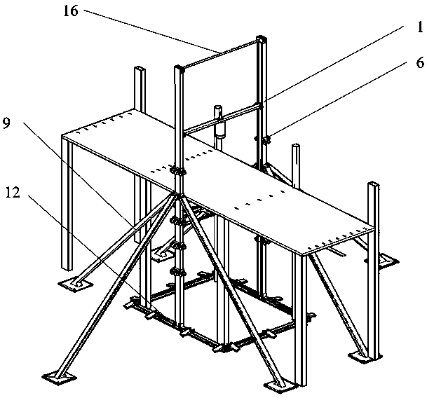
[0043] Such as Figure 1 to Figure 9 As shown, a mobile assembly type drop weight impact test device and installation method include a test bench, a drop weight 1 and a force sensor 5; the test bench is composed of a channel steel base 12, a guide rail 6, a support rod 9 and a steel beam 2 .

[0044] Such as Figure 4 to Figure 5 As shown, the channel steel base 12 is made up of four channel steels, the bottom of the channel steel base 12 is provided with a trapezoidal backing plate, and the channel steel is provided with a universal wheel clamp 13 at a distance. The guide rail 6 is vertically arranged on the channel steel base 12, and the guide rail 6 is provided with a convex connecting plate 8 at a certain distance, and the convex connecting plate 8 is provided with a rectangular groove.

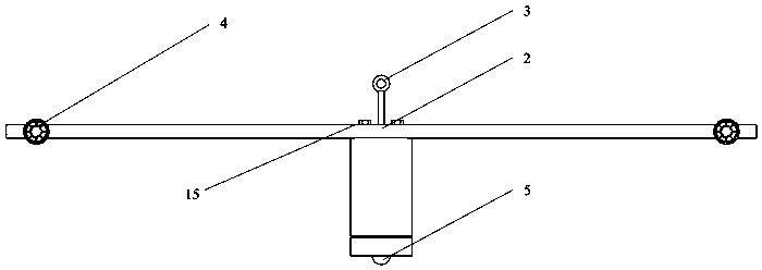
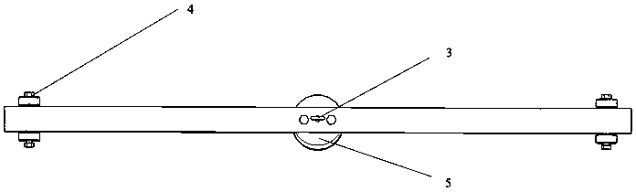
[0045] Such as Figure 2 to Figure 3 As shown, the long bolt 3 with a ring is fixed in the pre-drilled screw hole of the steel beam 2, and then the steel beam 2 is placed on the top su...

Embodiment 2

[0055] An installation method of a mobile assembly type drop weight impact test device, comprising using a mobile assembly type drop weight impact test device as in embodiment 1, such as Figure 1 to Figure 14 As shown, its installation method includes the following steps:

[0056] Step 1: Weld two steel plates on the channel steel base 12 . When installing the universal wheel module 4, pass a long screw through the outer ends of the two steel plates, string together with the universal wheel module 14, and then tighten the nut. Thread the second long screw through the inside end of the steel plate with a rectangular support plate welded in the middle of the screw. When the universal wheel module 14 rotates in the vertical plane, the rectangular support plate clamps the groove of the universal wheel module 14 to transmit the vertical support force of the ground. The guide rail 6 is respectively provided with a convex connecting plate 8 on each of the three surfaces at a certa...


PUM


Abstract

The invention relates to a mobile assembly type drop hammer impact test device and an installation method, and belongs to the technical field of impact resistance test. The device comprises a test bench, a drop hammer and a force sensor, the test bench is composed of a channel steel base, a guide rail, a supporting rod and a steel beam. The channel steel base is composed of four channel steels. The guide rail is vertically arranged on the channel steel base, convex connecting plates are arranged on the guide rail at intervals, and rectangular grooves are formed in the convex connecting plates;the steel beam is clamped between the guide rails and can slide up and down along grooves of the guide rails; one end of the supporting rod is inserted into the rectangular groove, and the other endis inserted into an inserting groove in a steel base plate laid on the ground; the drop hammer is fixed on the steel beam. The force sensor is fixed on the lower surface of the drop hammer. Compared with a traditional assembly type structure, many components of the device are easy to obtain on a construction site, on-site tests can be conducted in combination with on-site conditions, transportation cost is reduced, risks are reduced, economic benefits are improved, and convenience is brought.

Description

technical field [0001] The invention relates to a mobile assembly type drop weight impact test device and an installation method, belonging to the technical field of impact resistance performance testing. Background technique [0002] In many developed countries, prefabricated buildings are the most important way of building industrialization. It has many advantages such as improving quality, shortening construction period, saving energy, reducing consumption, and clean production. In response to the country's call for new urbanization with people as the core, the industrialization of prefabricated buildings will be pushed to a new stage. [0003] The drop weight impact test is a method for determining the response of concrete members to impact loads. Many tests at home and abroad are carried out in laboratories. Traditional test methods are difficult to ensure that the drop point of the impact hammer is precisely aligned with the center of the floor every time it falls; a...

Claims


Application Information

Patent Timeline
IPC IPC(8): G01N3/303G01N3/62
CPCG01N3/303G01N3/62G01N2203/0039
Inventor 胡少伟许毅成喻江薛翔张润张云豪
Owner NANJING HYDRAULIC RES INST
Why Eureka
Try Eureka