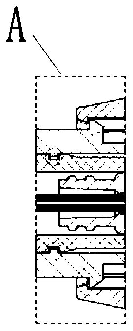
Multifunctional vertebral body former
A vertebroplasty and multifunctional technology, which is applied in the field of medical devices, can solve the problems of not disclosing the connection relationship and working mode of the proximal end in detail, and achieve the effect of reducing surgical steps, simple and convenient operation, and reducing the number
- Summary
- Abstract
- Description
- Claims
- Application Information
AI Technical Summary
Problems solved by technology
Method used
Image
Examples
Embodiment 1
[0066] This embodiment provides a multifunctional vertebral body shaper, such as figure 1 , 2a -2b and 3a-3b, which include
[0067] A balloon structure 1, which includes a balloon outer tube 16, a balloon handle 11 and a balloon 15; the proximal outer surface of the balloon outer tube 16 is sequentially sleeved with a balloon handle fitting 12, the The balloon handle 11 and the balloon delivery buckle 13; wherein, the balloon handle 11 and the balloon delivery buckle 13 pass through the fourth lug 132 on the balloon delivery buckle 13 and the buckle on the balloon handle 11 The grooves are matched to be rotatable and fixed; the balloon handle fitting 12 is fixedly connected to the balloon handle 11; the distal end of the balloon outer tube 16 is fixedly connected to the balloon 15, and the distal end of the balloon 15 is sealed ;
[0068] A delivery tube structure 2, comprising a shape memory alloy tube 21, a slider 23 and an outer tube adjustment handle 22, the shape memo...
Embodiment 2
[0085] This embodiment provides the working principle of the multifunctional vertebral body shaper described in Embodiment 1.
[0086] (1) Before the operation starts, if Figure 2a , 3a , 5, and 14-15, the delivery tube structure 2 is connected to the outside of the balloon set structure 1 through buckles, and the first lug 231 on the slider 23 is set on the far end of the balloon delivery buckle 13. On the card slot, the third lug 143 on the balloon delivery buckle fitting 14 is clamped on the limit card slot 241 on the limit member 24; figure 1 with Figure 5 As shown, after the working channel is established, the multifunctional vertebral body shaper provided in embodiment 1 is inserted into the working sleeve structure 3, and the locking ring 26 is rotated to connect the multifunctional vertebral body shaper to the working sleeve structure 3. Sleeve handle 31 is fixed;
[0087] (2) if Figure 10a As shown, turn the outer tube adjustment handle 22 clockwise, the outer...
Embodiment 3
[0094] This embodiment provides the working principle of the multifunctional vertebral body shaper described in Embodiment 1.
[0095] (1) Before the operation starts, if Figure 2a , 3a , 5, and 14-15, the delivery tube structure 2 is connected to the outside of the balloon structure 1 through buckles, and the first lug 231 on the slider 23 is set at the far end of the balloon delivery buckle 13. On the groove, the third lug 143 on the balloon delivery buckle fitting 14 is set on the limit card groove 241 on the limit member 24; figure 1 with Figure 5 As shown, after the working channel is established, the multifunctional vertebral body shaper provided in embodiment 1 is inserted into the working sleeve structure 3, and the locking ring 26 is rotated to connect the multifunctional vertebral body shaper to the working sleeve structure 3. Sleeve handle 31 is fixed;
[0096] (2) if Figure 10b As shown, turn the outer tube adjustment handle 22 clockwise, and drive the ball...
PUM
 Abstract
Description
Claims
Application Information
 - R&D
- Intellectual Property
- Life Sciences
- Materials
- Tech Scout
- Unparalleled Data Quality
- Higher Quality Content
- 60% Fewer Hallucinations
Browse by: Latest US Patents, China's latest patents, Technical Efficacy Thesaurus, Application Domain, Technology Topic, Popular Technical Reports.
© 2025 PatSnap. All rights reserved.Legal|Privacy policy|Modern Slavery Act Transparency Statement|Sitemap|About US| Contact US: help@patsnap.com


