Centrifugal pump shell processing clamp

A centrifugal pump and casing technology, applied in the field of centrifugal pump production, can solve the problems of centrifugal pump casing fixtures such as single function, insufficient practicability, and poor operation coordination effect, and achieve compact structure, convenient processing operation, and smooth operation Effect

Active Publication Date: 2020-03-24
哈尔滨凯泉泵业有限公司
View PDF8 Cites 3 Cited by
  • Summary
  • Abstract
  • Description
  • Claims
  • Application Information

AI Technical Summary

Problems solved by technology

[0004] 1. The fixture of the centrifugal pump casing has a single function. Generally, it only has the function of clamping and positioning, and requires a pump body with multiple processing surfaces perpendicular to the same reference plane. The practicability is not wide enough.
[0005] 2. The centrifugal pump casing fixture is equipped with a multi-stage angle adjustment mechanism. The secondary angle adjustment mechanism requires additional equipment to adjust the angle of the pump body. The space utilization rate is low, and the operation of each structure is poor.

Method used


Image

  • Centrifugal pump shell processing clamp
  • Centrifugal pump shell processing clamp
  • Centrifugal pump shell processing clamp

Examples


Embodiment 1

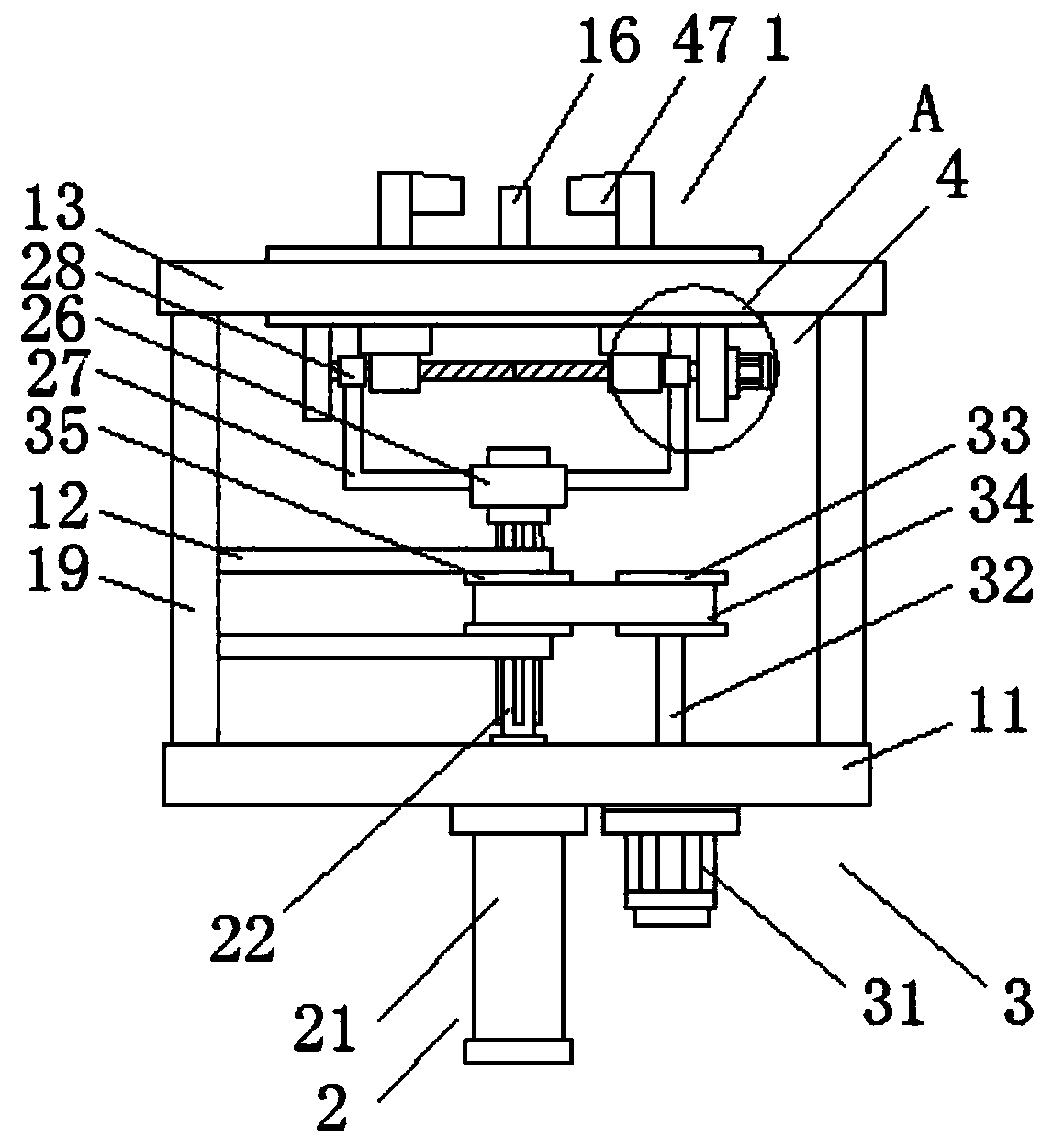
[0025] Embodiment 1: as Figure 1-6 As shown, this specific embodiment adopts the following technical solutions: a centrifugal pump casing processing fixture, including a fixed frame 1, a pressing mechanism 2, a rotating mechanism 3 and a clamping mechanism 4, and a pressing mechanism 2 is installed in the fixed frame 1 , the rotating mechanism 3 and the clamping mechanism 4, the rotating mechanism 3 is connected with the pressing mechanism 2, and the pressing mechanism 2 is connected with the clamping mechanism 4.

[0026] Wherein, fixed frame 1 comprises base plate 11, support plate 12, fixed plate 13, chute 14, threaded hole 15, positioning rod 16, rectangular frame 17, rotating tray 18 and connecting plate 19, and the top of base plate 11 is provided with fixed plate 13 , between the bottom plate 11 and the fixed plate 13 are fixedly connected with two connecting plates 19, one of which is fixedly connected with two supporting plates 12 on the side wall of the connecting p...

Embodiment 2

[0035] Embodiment 2: In this embodiment, the clamping model of the centrifugal pump body is installed at the end of the clamping hook 47 in the first embodiment. Through the setting of two and a half models, the No. 2 motor 41 is started to drive the No. 2 rotating shaft 42 Rotate, the external thread 44 is threaded with the threaded sleeve 45, and under the limit action of the No. 1 slider 46, when the two clamping hooks 47 are close to each other, the two half-models are respectively clamped on the irregular surfaces on both sides of the centrifugal pump. In this way, the centrifugal pump can be effectively positioned and clamped, and the outer wall of the centrifugal pump can be treated more comprehensively. A friction coupling is connected between the output shaft of the second motor 41 and the second rotating shaft 42, which can effectively avoid overloading of the clamping action. , causing the second motor 41 or the external thread 44 to be damaged.


PUM


Abstract

The invention discloses a centrifugal pump shell processing clamp which comprises a fixed frame, a compressing mechanism, a rotary mechanism and a clamping mechanism, wherein the compressing mechanism, the rotary mechanism and the clamping mechanism are mounted in the fixed frame; the rotary mechanism is connected with the compressing mechanism; the compressing mechanism is connected with the clamping mechanism; the fixed frame comprises a bottom plate, a support plate, a fixed plate, a sliding chute, a threaded hole, a positioning rod, a rectangular frame, a rotary tray and a connecting plate; the compressing mechanism, the rotary mechanism and the clamping mechanism are sequentially combined; a connecting sleeve is arranged to meet the rotary requirement of a second rotary shaft; a limiting sliding strip and a straight groove are arranged to meet the sliding requirement of a lantern ring when a central rotary shaft rotates, so that all mechanisms run independently; all running mechanisms do not need to load the weight of other driving equipment and are excellent in cooperating effect, and the space utilization ratio is high; and a pump body is fixed through a fixing flange, so that the defect that only a specific clamping model can effectively fix the pump body is avoided.

Description

Technical field: [0001] The invention belongs to clamping equipment, in particular to a clamp for processing a centrifugal pump casing, and belongs to the technical field of centrifugal pump production. Background technique: [0002] Centrifugal pump parts are complex in structure, castings account for more than 80%, mainly cast iron, cast steel and cast stainless steel parts, shaft parts are less, mainly high-quality carbon steel, chrome steel or stainless steel parts, during the processing of centrifugal pump parts , because it has a hydraulic flow channel, when considering the positioning of the clamping reference, the correct position of the flow channel must be found to avoid deflection, dislocation, uneven gap or even friction between the pressurized water chamber and the impeller flow channel after assembly, which will affect the product Quality, in order to ensure the manufacturing accuracy of parts, it is necessary to design corresponding tooling and arrange the pro...

Claims


Application Information

Patent Timeline
Patent Type & Authority Applications(China)
IPC IPC(8): B23Q3/00B23Q3/08B23Q7/00
CPCB23Q3/00B23Q3/062B23Q3/08B23Q7/00B23Q2703/04
Inventor 孟萍
Owner 哈尔滨凯泉泵业有限公司
Why Eureka
Try Eureka